Self-balancing liquid pumping device, flooded evaporating device and its refrigeration system

An evaporating device and self-balancing technology, which is applied in the direction of refrigerators, refrigeration components, refrigeration and liquefaction, etc., can solve the problems of difficult to effectively control the liquid level, low precision of pump liquid control, complex overall structure of the system, etc., to achieve convenient The effects of industrial application, good versatility and practicality, and broad market prospects

Active Publication Date: 2021-09-28
赖邦跃
View PDF6 Cites 0 Cited by
  • Summary
  • Abstract
  • Description
  • Claims
  • Application Information

AI Technical Summary

Problems solved by technology

[0012] The object of the present invention is to provide a self-balancing liquid pumping device and a flooded evaporator using the self-balancing pumping device, so as to solve the problem that each functional component is independent of each other in the overall structure of the existing flooded pump liquid supply system. , The overall structure of the system is complex, the pump liquid control accuracy is not high, and the liquid level height is difficult to be effectively controlled

Method used


Image

  • Self-balancing liquid pumping device, flooded evaporating device and its refrigeration system
  • Self-balancing liquid pumping device, flooded evaporating device and its refrigeration system
  • Self-balancing liquid pumping device, flooded evaporating device and its refrigeration system

Examples


Embodiment 2

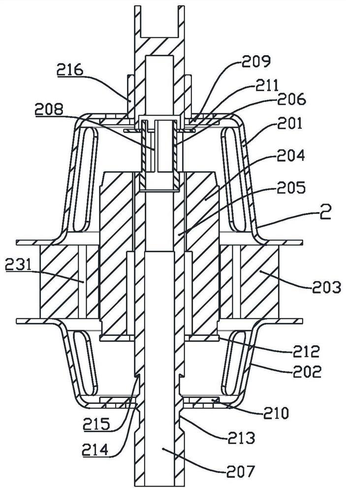
[0071] In this embodiment, an annular boss 214 is provided on the rotating shaft 205 in the annular groove 213 , and a certain gap is set between the annular boss 214 and the valve sleeve. An annular flow equalizing ring channel is formed between the outer ring end face of the annular boss 214 and the valve sleeve. After the refrigerant enters the annular groove, it moves toward the top of the annular groove through the equalizing ring. The arrangement of the equalizing ring structure can ensure The uniformity of the fluid flow direction within the annular groove.

[0072] The upper part of the ring groove 213 forms a backwater bay 215 with a triangular annular cross-section on the rotating shaft, and the backwater bay forms a cavity structure on the rotating shaft that opens toward the direction of the ring groove. An inner chamfer structure that slopes downward is formed. When the liquid in the ring groove 213 is continuously flowing upward, it interacts with the backwater ...

Embodiment 3

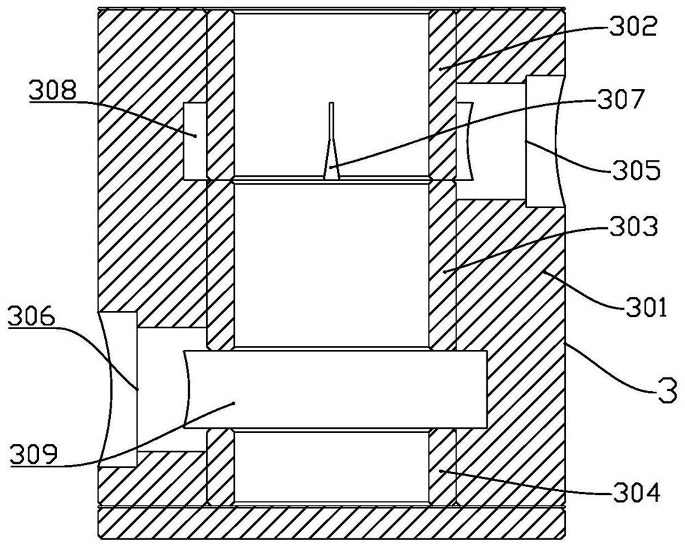
[0074] In this embodiment, the valve body 301 is provided with a horizontal first annular groove 308 on the plane where the liquid supply port is located, and the first annular groove 308 communicates with the liquid supply port 305 . The first annular groove is used to connect the liquid supply port and the throttling opening, and the annular structure of the first annular groove can transition and buffer the high-pressure fluid entering through the liquid supply port, so as to reduce the pressure of the high-pressure liquid and the impact on the rotation of the rotating shaft. influences. A horizontal second annular groove 309 is provided in the valve body 301 on the plane where the pump liquid port is located, and the second annular groove 309 is respectively communicated with the pump liquid port 306 and the inside of the valve sleeve. By arranging the second annular groove, the annular structure of the second annular groove also plays the role of transitioning and bufferi...

Embodiment 4

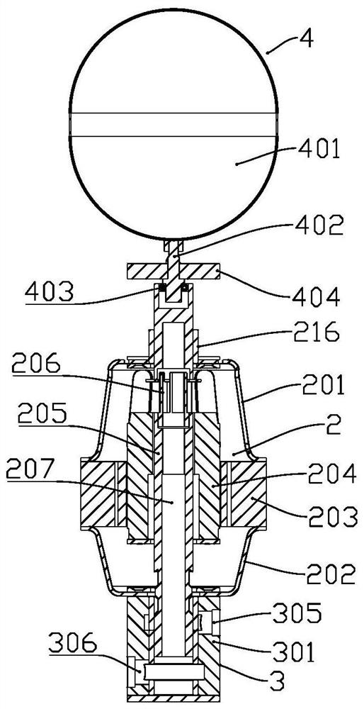
[0078] like Figure 5 In the flooded evaporation device of the present invention, the valve body 301 of the self-balancing pump liquid device is arranged outside the tank body 101, the upper end of the valve body 301 is fixedly connected to the tank body 101, and the bottom of the tank body 101 and the upper end face of the valve body 301 are connected sealed connection.

[0079] Specifically, the bottom of the tank body 101 is provided with an opening, the valve body 301 is arranged below the opening of the tank body 101, and the valve body 301 is sealed and connected between the opening end of the valve cavity and the tank body 101, so that there is a gap between the valve cavity and the tank body. communicated to form a sealed cavity.

[0080] The working process of the flooded evaporation device in this embodiment will be described below with reference to the structure and working principle of the flooded evaporation device. The device realizes the precise control of the ...


PUM


Abstract

The invention discloses a self-balancing liquid pumping device, a flooded evaporating device and a refrigeration system adopting the self-balancing liquid pumping device. Functional components, float level control functional components, expansion valve functional components, automatic oil return functional components and tanks for storing refrigerant are integrated into one body, which makes the device have a good structural integrity and facilitates the industrial application of the device , has good versatility and practicability, and has the functions of pumping liquid for the evaporator, accurately controlling the flow rate of the pump liquid, accurately controlling the height of the liquid level in the tank, and accurately controlling the throttling amount, etc. It can be applied to various evaporative refrigeration fields , can realize the replacement of traditional dry thermal expansion evaporation technology with flooded evaporation technology, greatly improve refrigeration efficiency, and have broad market prospects.

Description

technical field [0001] The invention relates to the technical field of refrigeration, in particular to a self-balancing liquid pump device, a flooded evaporation device and a refrigeration system thereof. Background technique [0002] In the vapor compression refrigeration system, the liquid supply methods of the refrigeration system include dry thermal expansion direct liquid supply and flooded liquid supply. Dry thermal expansion direct liquid supply is divided into three types: thermal expansion valve, capillary tube and electronic expansion valve. The dry thermal expansion direct liquid supply method is suitable for small and medium-sized refrigeration systems; the flooded liquid supply is divided into gravity liquid supply and flooded liquid supply. Pump liquid supply, gravity liquid supply is similar to flooded pump liquid supply, suitable for large-scale single-storey refrigeration systems. The flooded pump liquid supply method is suitable for large-scale systems, es...

Claims


Application Information

Patent Timeline
Patent Type & Authority Patents(China)
IPC IPC(8): F25B1/08F25B31/00F25B41/31F25B41/20F25B43/00F25B49/02
CPCF25B1/08F25B49/02F25B31/004F25B43/006F25B41/20F25B41/31
Inventor 赖邦跃
Owner 赖邦跃
Why Eureka
Try Eureka