Supercharge Your Innovation With Domain-Expert AI Agents!

Three-dimensional modeling method and system based on 3D visual sensor

A visual sensor, 3D modeling technology, applied in the field of robotics, can solve problems such as inaccurate positioning

Pending Publication Date: 2020-07-07
SHENYANG SIASUN ROBOT & AUTOMATION
View PDF3 Cites 0 Cited by
  • Summary
  • Abstract
  • Description
  • Claims
  • Application Information

AI Technical Summary

Problems solved by technology

[0003] In view of this, the embodiment of the present application provides a 3D modeling method and system based on a 3D vision sensor to solve the problem of positioning the object through the built model when the position of the object changes in the modeling method used in the prior art. There will be problems with inaccurate positioning

Method used


Image

  • Three-dimensional modeling method and system based on 3D visual sensor
  • Three-dimensional modeling method and system based on 3D visual sensor
  • Three-dimensional modeling method and system based on 3D visual sensor

Examples


Embodiment 1

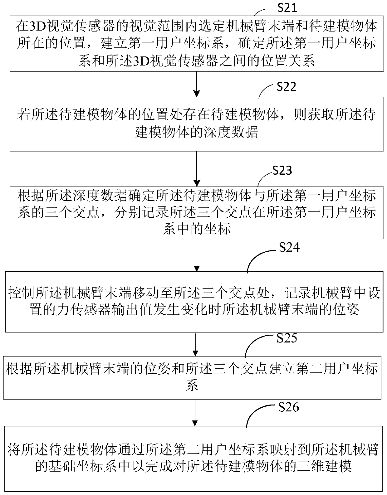
[0057] figure 2 It shows a schematic diagram of the implementation flow of a 3D visual sensor-based three-dimensional modeling method provided by the embodiment of the present application, including steps S21-step S24, wherein:

[0058] Step S21, select the position of the end of the robotic arm and the object to be modeled within the visual range of the 3D vision sensor, establish a first user coordinate system, and determine the position between the first user coordinate system and the 3D vision sensor relation.

[0059] In the modeling method provided by this application, the modeling scene is first set up, specifically, the positions of the end of the manipulator and the object to be modeled are selected within the modeling range, or the end of the manipulator equipped with a three-dimensional force sensor and the position of the object to be modeled are selected. The model objects are respectively fixed at a point within the field of view of the 3D vision sensor, and th...

Embodiment 2

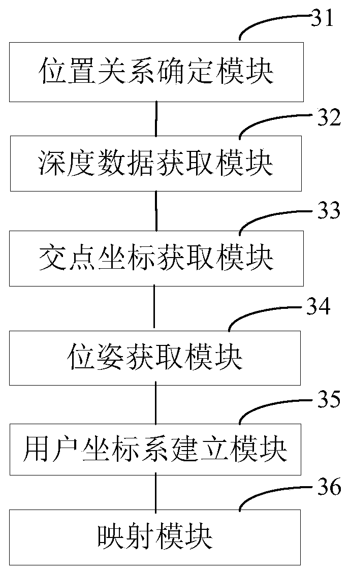
[0089] image 3 A schematic structural diagram of a 3D modeling system based on a 3D vision sensor provided in another embodiment of the present application is shown, and the system includes:

[0090] The position relationship determination module 31 is used to select the position of the end of the mechanical arm and the object to be modeled within the visual range of the 3D vision sensor, establish a first user coordinate system, and determine the first user coordinate system and the 3D vision The positional relationship between the sensors;

[0091] A depth data acquisition module 32, configured to acquire depth data of the object to be modeled when there is an object to be modeled at the position of the object to be modeled;

[0092] An intersection coordinate acquisition module 33, configured to determine three intersection points between the object to be modeled and the first user coordinate system according to the depth data, and respectively record the three intersecti...


PUM


Abstract

The invention relates to the technical field of robots, and particularly discloses a three-dimensional modeling method and system based on a 3D visual sensor, and the method comprises: selecting the tail end of a mechanical arm and the position of a to-be-modeled object in a visual range of the 3D visual sensor, building a first user coordinate system, and obtaining the depth data of the to-be-modeled object; determining three intersection points of the to-be-modeled object and the first user coordinate system; controlling the tail end of the mechanical arm to move to the three intersection points, and recording the pose of the tail end of the mechanical arm when the output value of the force sensor changes; establishing a second user coordinate system; and mapping a to-be-modeled object to a basic coordinate system of the mechanical arm through the second user coordinate system for three-dimensional modeling. According to the method for recalibrating the user coordinate system on theto-be-modeled object, by means of the characteristic that the repeated positioning precision of the robot is high, when the position of the to-be-modeled object is greatly changed, errors caused by low absolute positioning precision of the robot are reduced, and the three-dimensional modeling precision of the robot is improved.

Description

technical field [0001] The present application relates to the field of robot technology, in particular to a 3D modeling method and system based on a 3D vision sensor. Background technique [0002] In the process of implementing the three-dimensional modeling of the object based on the basic coordinate system by the robot, when the position of the object changes greatly, since the origin of the user coordinate system is not on the object, and the absolute positioning accuracy of the robot is lower than the repeated positioning accuracy of the robot, in this way, when the object is controlled by the robot In the process of 3D modeling based on the basic coordinate system, large errors will occur, which will affect the 3D modeling and subsequent positioning and grasping operations. Contents of the invention [0003] In view of this, the embodiment of the present application provides a 3D modeling method and system based on a 3D vision sensor to solve the problem of positionin...

Claims


Application Information

Patent Timeline
Patent Type & Authority Applications(China)
IPC IPC(8): G06T17/00G06T19/00B25J9/16
CPCG06T17/00G06T19/003B25J9/1605G06T2219/2004
Inventor 徐方陈亮王晓东姜楠潘鑫宋健
Owner SHENYANG SIASUN ROBOT & AUTOMATION
Features
  • R&D
  • Intellectual Property
  • Life Sciences
  • Materials
  • Tech Scout
  • Unparalleled Data Quality
  • Higher Quality Content
  • 60% Fewer Hallucinations
Learn More