
Dry-type transformer

A technology for dry-type transformers and high-voltage windings, which is applied to transformer/inductor components, transformer/inductor coils/windings/connections, electrical components, etc., and can solve problems such as discharge, large insulation distance, and increased cost of dry-type transformers

Pending Publication Date: 2020-07-07
山东迅驰电气有限公司
View PDF0 Cites 0 Cited by
  • Summary
  • Abstract
  • Description
  • Claims
  • Application Information

AI Technical Summary

Problems solved by technology

[0002] At present, in the 6-66kV voltage level dry-type transformers in use, the main body of the transformer is mainly composed of iron core, low-voltage winding, intermediate insulating cylinder and high-voltage winding. The high-voltage winding is a copper wire wound layer or continuous structure. After the winding is completed, it is casted with epoxy resin. The insulation system between the low-voltage winding and the high-voltage winding is composed of air, intermediate insulating cylinder and air from the core side from the inside to the outside. Since the dielectric constant of air is 1, the middle The dielectric constant of the insulating cylinder is about 5. As a part of the insulation system, the electrical insulation strength of the air is very poor; The phenomenon of discharge due to poor insulation strength; in order to ensure the electrical insulation strength, the insulation distance between low voltage and high voltage is often placed very large, resulting in an increase in the cost of dry-type transformers

Method used


Image

  • Dry-type transformer
  • Dry-type transformer
  • Dry-type transformer

Examples


Embodiment Construction

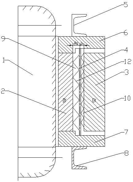
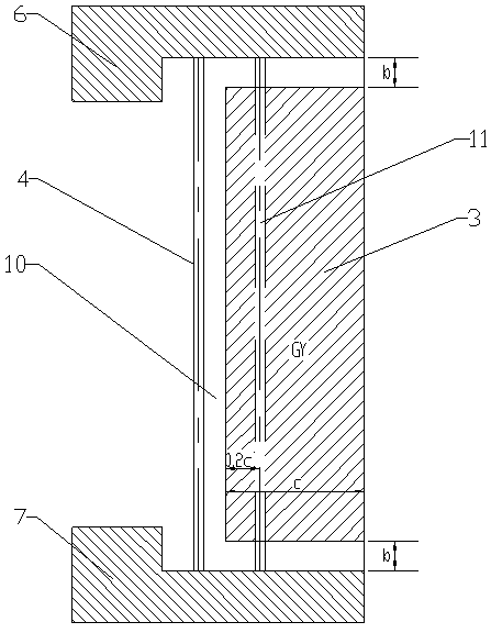
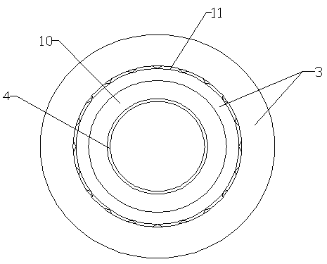
[0023] Accompanying drawing is the specific embodiment of the present invention. Such as Figure 1 to Figure 3 As shown, this kind of dry-type transformer includes an iron core 1, on which a low-voltage winding 2 and a high-voltage winding 3 are wound sequentially from the inside to the outside, and the high-voltage winding 3 and the low-voltage winding 2 pass through the upper clamp 5 and the upper pad 6. The lower clamp 8 and the lower pad 7 are fixed, wherein:

[0024] Add an additional high-voltage winding insulating layer 4 between the high-voltage winding 3 and the low-voltage winding 2, the upper and lower pads 6 of the high-voltage winding additional insulating layer 4, and the lower top and lower pads 7, between the low-voltage winding 2 and the high-voltage winding additional insulating layer 4 The spacer layer 10 is formed between the additional insulating layer 4 of the high-voltage winding and the high-voltage winding 3 through the support frame 12, and the dista...


PUM


Abstract

The invention relates to the field of power supply line facilities, and particularly discloses a dry-type transformer. The transformer comprises an iron core, wherein a low-voltage winding and a high-voltage winding are sequentially wound on the iron core from inside to outside; the high-voltage winding and the low-voltage winding are fixed through an upper clamping part, an upper cushion block, alower clamping part and a lower cushion block. The transformer is characterized in that a high-voltage winding additional insulating layer is arranged on the inner side of the high-voltage winding, aspacing layer is reserved between the high-voltage winding and the high-voltage winding additional insulating layer, and an air isolation layer is arranged between the low-voltage winding and the high-voltage winding; an air channel layer is arranged in the high-voltage winding, and the high-voltage winding and the high-voltage winding additional insulating layer are integrally formed through epoxy resin pouring. The electrical insulation strength between the low-voltage winding and the high-voltage winding is remarkably enhanced, and the comprehensive cost of the transformer is greatly reduced.

Description

technical field [0001] The invention relates to the field of power supply line facilities, in particular to a dry-type transformer. Background technique [0002] At present, in the 6-66kV voltage level dry-type transformers in use, the main body of the transformer is mainly composed of iron core, low-voltage winding, intermediate insulating cylinder and high-voltage winding. The high-voltage winding is a copper wire wound layer or continuous structure. After the winding is completed, it is casted with epoxy resin. The insulation system between the low-voltage winding and the high-voltage winding is composed of air, intermediate insulating cylinder and air from the core side from the inside to the outside. Since the dielectric constant of air is 1, the middle The dielectric constant of the insulating cylinder is about 5. As a part of the insulation system, the electrical insulation strength of the air is very poor; The phenomenon of discharge due to poor insulation strength;...

Claims


Application Information

Patent Timeline
Patent Type & Authority Applications(China)
IPC IPC(8): H01F27/28H01F27/32
CPCH01F27/2876H01F27/324H01F27/327
Inventor 刘余顺庞明杰李环李先亮陈爱云
Owner 山东迅驰电气有限公司
Learn More