A reactor coil with reinforced interlayer insulation structure

An interlayer insulation and reactor technology, applied in the direction of transformer/inductor coil/winding/connection, etc., can solve the problems of not effectively strengthening the end insulation, low coil filling factor, hidden quality problems, etc. High efficiency, stable product performance and easy operation

Inactive Publication Date: 2017-07-25
KUNSHAN SPECIAL TRANSFORMER MFR
View PDF6 Cites 0 Cited by
  • Summary
  • Abstract
  • Description
  • Claims
  • Application Information

AI Technical Summary

Problems solved by technology

Segmented multi-layer structure: Coil winding will be very troublesome, and it will take a lot of man-hours; additional inter-segment insulation 4 is required inside the coil, resulting in a low filling factor of the coil and a significant increase in material cost; many coils will appear inside the coil Welding joints required by the process, such as figure 1 As shown in the coil process joint 5 in , there are hidden quality problems; there are still high voltages at both ends of the coil, and the insulation at the ends has not been effectively strengthened

Method used


Image

  • A reactor coil with reinforced interlayer insulation structure
  • A reactor coil with reinforced interlayer insulation structure
  • A reactor coil with reinforced interlayer insulation structure

Examples


specific Embodiment approach

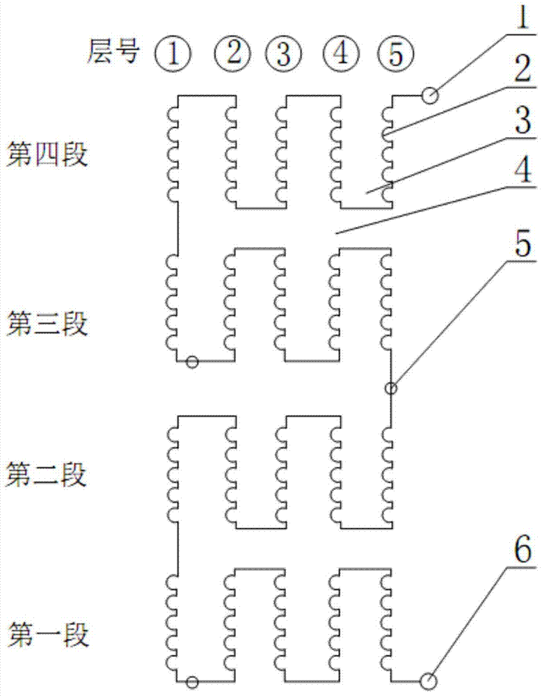
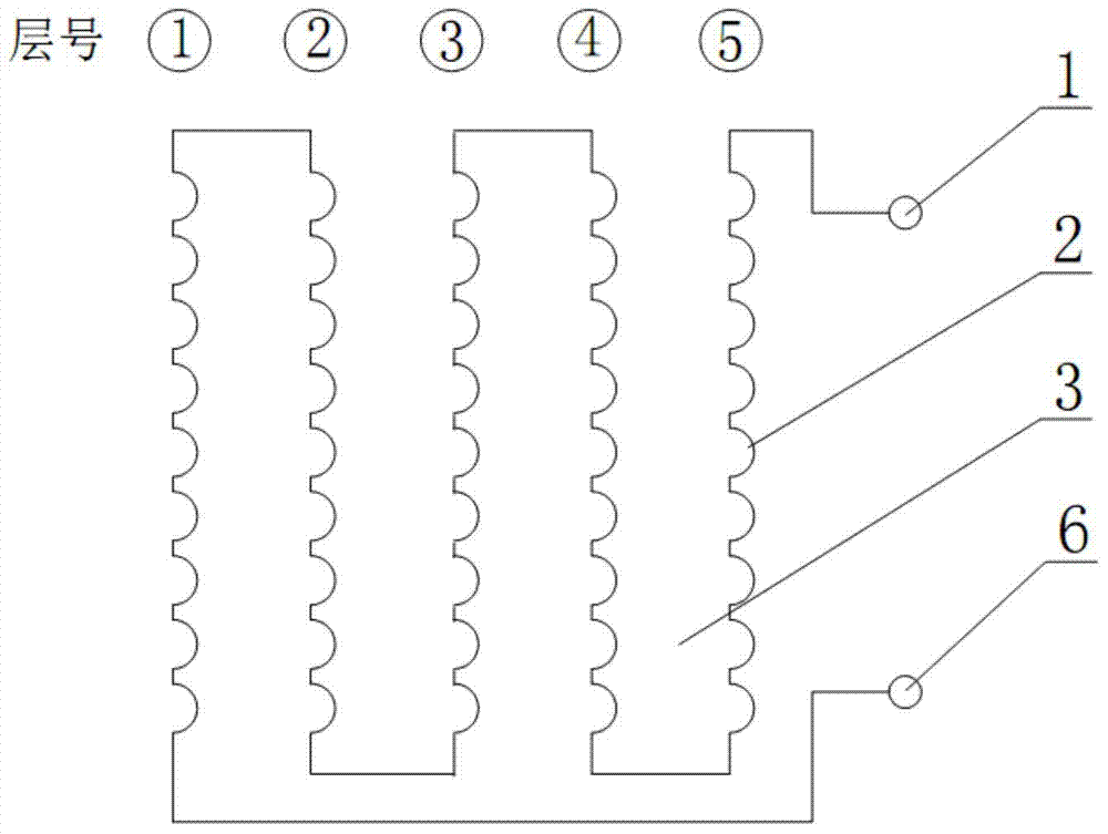
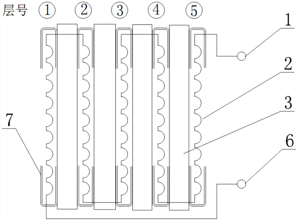
[0040] The specific implementation method: wrap the insulating film 7 on the entire circumference of the two ends of each layer of winding coil. Generally, each end of the winding coil is wrapped with the insulating film 7 of the entire circumference. It is divided into two sections along the circumference and wrapped respectively. overlay. First, prepare enough insulating film with a length longer than half of the circumference of the layer and a certain width for each layer of winding coil. When winding the beginning of each layer of winding coil, press half of the width of the insulating film along the entire circumference. After winding to a certain number of turns, turn the other half of the width of the insulating film upwards to cover the top of the turns. The insulating film is turned up in two sections along the circle, which is more convenient. In this way, the beginning of each layer of winding coil is completely wrapped by the insulating film on the entire circumfe...


PUM


Abstract

The invention discloses electric reactor coils of a reinforced interlayer insulation structure. The electric reactor coils of the reinforced interlayer insulation structure comprise multiple layers of winding coils, interlayer insulation and insulating films, wherein the multiple layers of the winding coils are arranged around an electric reactor magnetic leg in a spaced and enveloping mode, each layer of the winding coil is arranged in a spaced and overlaid mode, and all the layers of the winding coils are connected with one another in series; the interlayer insulation is arranged between the two adjacent layers of the winding coils, the insulating films are arranged at the head end and the tail end of each layer of the winding coil in a covering mode, the insulating films are each shaped like a rectangle, each insulating film is folded in half along the center line in the width direction, each center line portion abuts against the end of each layer of the winding coil, and the two folded edges of each insulating film extend to the interior of the corresponding winding coil for a certain distance and wrap multiple numbers of coils at the end of each layer of the winding coil. According to the electric reactor coils of the reinforced interlayer insulation structure, the technical problem that interlayer breakdown occurs at the two ends of the coils is solved, and the insulating strength of the coils is improved.

Description

technical field [0001] The invention belongs to the technical field of high-voltage electrical equipment, in particular to a reactor coil with a reinforced interlayer insulation structure. Background technique [0002] Iron core series reactor coil, the coil terminal voltage is not high during normal operation, and the number of coil turns is very small. 10KV voltage level coil: the terminal voltage ranges from tens of volts to several hundred volts; 20KV voltage level coil: the terminal voltage ranges from several hundred volts to more than one thousand volts; 35KV voltage level coil: the terminal voltage ranges from several hundred volts to three It varies within a thousand volts. However, at the moment of closing and opening, the short-term impulse voltage that the coil bears is extremely high. 10KV voltage level: the coil withstands a short-term impulse voltage up to 50KV-75KV; 20KV voltage level: the coil withstands a short-term impulse voltage up to 100KV-125KV; 35KV...

Claims


Application Information

Patent Timeline
Patent Type & Authority Patents(China)
IPC IPC(8): H01F27/32
Inventor 杨胜生
Owner KUNSHAN SPECIAL TRANSFORMER MFR
Why Eureka
Try Eureka