
Plastic fiber infiltrating irrigation pipe

A technology of plastic fiber and infiltration irrigation pipe, applied in the field of infiltration irrigation pipe, can solve the problems of resource waste adjustment, increase labor intensity and cost, cumbersome and other problems, and achieve the effects of long water outlet distance, improved use range, and quick and convenient installation.

Inactive Publication Date: 2020-07-10
唐杰
View PDF0 Cites 1 Cited by
  • Summary
  • Abstract
  • Description
  • Claims
  • Application Information

AI Technical Summary

Problems solved by technology

[0003] When the existing seepage irrigation pipes are used, they are directly buried in the ground, and the liquid seeps out from the seepage holes through the pressure of water pressure to complete the irrigation. However, when the length of the seepage irrigation pipes is not enough, it needs Use joints to connect them. The existing joints are directly fastened with screw buckles. The fixing needs to add buckles at the port of the infiltration and irrigation pipe, which increases labor intensity and cost. At the same time, the infiltration and irrigation pipe has leakage. The irrigation volume can only be adjusted by the pore size, and the infiltration irrigation pipe needs to be replaced during the adjustment, resulting in waste of resources and cumbersome adjustments. For this reason, we propose a plastic fiber infiltration irrigation pipe

Method used


Image

  • Plastic fiber infiltrating irrigation pipe
  • Plastic fiber infiltrating irrigation pipe
  • Plastic fiber infiltrating irrigation pipe

Examples


Embodiment Construction

[0023] In order to make the technical means, creative features, goals and effects achieved by the present invention easy to understand, the present invention will be further described below in conjunction with specific embodiments.

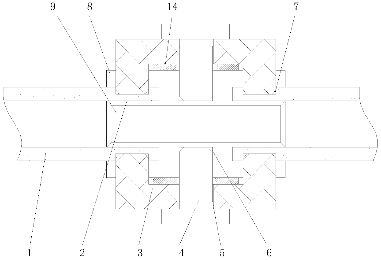
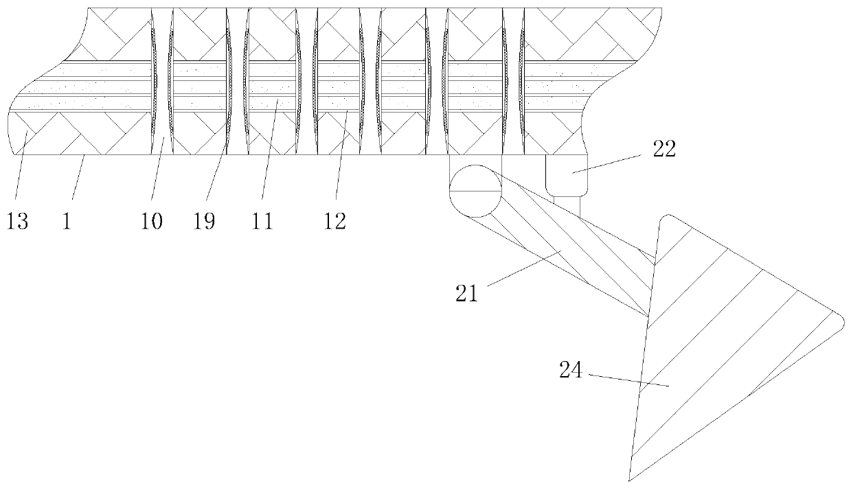
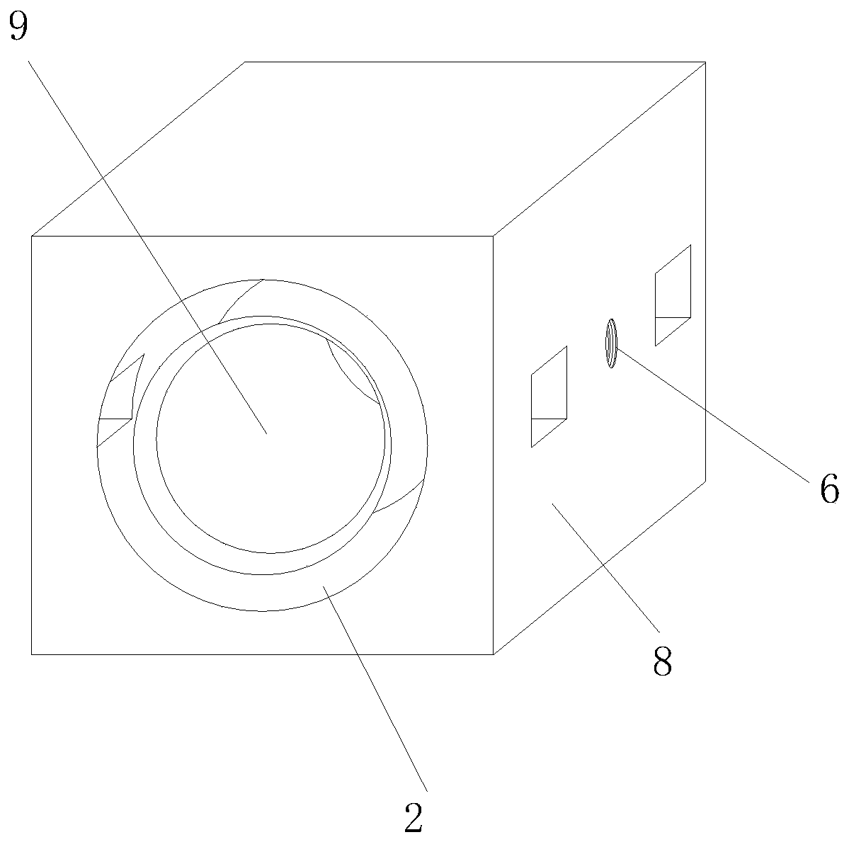
[0024] Such as figure 1 with Figure 5 As shown, a plastic fiber permeation irrigation pipe according to the present invention includes an installation block 8, and both sides of the installation block 8 are provided with installation grooves 2, and the interior of the installation groove 2 is provided with an infiltration irrigation pipe 1. The outer wall of the end of the seepage irrigation pipe 1 is provided with a circular groove 7, and both ends of the outer wall of the installation block 8 are provided with a fixed block 3, and the end of the fixed block 3 passes through the surface of the installation block 8 and interacts with the annular groove 7. connection, the surface of the mounting block 8 is provided with a water hole 9; the surfac...


PUM


Abstract

The invention belongs to the technical field of infiltrating irrigation pipes, and specifically relates to a plastic fiber infiltrating irrigation pipe. The plastic fiber infiltrating irrigation pipecomprises a mounting block, wherein a mounting groove is respectively arranged at two sides of the mounting block; an infiltrating irrigation pipe is arranged in each mounting groove in a sleeving mode; an annular groove is arranged on the outer wall of the end part of each infiltrating irrigation pipe; a fixed block is respectively arranged at two ends of the outer wall of the mounting block; theend part of each fixed block penetrates through the surface of the mounting block and is connected with an annular groove; and a water flowing hole is arranged on the surface of the mounting block. According to the invention, through the designed mounting block, two infiltrating irrigation pipes can be connected into a whole; through the designed mounting grooves, the end openings of the infiltrating irrigation pipes can be conveniently connected with and arranged on the mounting block in a sleeving mode, so follow-up connection is facilitated; through the designed fixed blocks, the fixed block can penetrate through the mounting block to be clamped in the annular grooves arranged on the infiltrating irrigation pipe, so the infiltrating irrigation pipe is tightly clamped on the mounting block, and the infiltrating irrigation pipe is mounted more quickly and conveniently; meanwhile, the infiltrating irrigation amount of each section of the infiltrating irrigation pipe can be adjusted.

Description

technical field [0001] The invention belongs to the technical field of seepage irrigation pipes, in particular to a plastic fiber seepage irrigation pipe. Background technique [0002] Seepage irrigation, that is, underground irrigation, is an irrigation method that uses underground pipes to input irrigation water into the field and bury it in a seepage pipe or rat hole at a certain depth underground, and moistens the soil with the help of soil capillary action. my country is a water-poor country with relatively scarce water resources. . High-efficiency water-saving irrigation technology is an effective means to solve the shortage of water resources, and infiltration irrigation technology is one of the most potential technologies for high-efficiency water-saving irrigation. [0003] When the existing seepage irrigation pipes are used, they are directly buried in the ground, and through the pressure of water pressure, the liquid seeps out from the seepage holes to complete th...

Claims


Application Information

Patent Timeline
IPC IPC(8): A01G25/06A01G25/16F16B7/08
CPCA01G25/06A01G25/16F16B7/00
Inventor 唐杰吴爱兵汪通鲜
Owner 唐杰
Learn More