Foundation pile high-strain hammering system

A high-strain, hammering technology, applied in sheet pile walls, foundation structure engineering, foundation structure tests, etc., can solve problems such as low operating efficiency, difficult installation, and the inability of the hammering device to connect pile ends in real time, achieving The effect of reducing size and height

Pending Publication Date: 2020-05-22
淮安市建筑工程质量检测中心有限公司
View PDF0 Cites 2 Cited by
  • Summary
  • Abstract
  • Description
  • Claims
  • Application Information

AI Technical Summary

Problems solved by technology

[0004] The purpose of the present invention is to provide a high-strain hammering system for foundation piles, which overcomes the defects of the prior art, solves the problems of unstable connection between the excavator bucket and the hammering device, prone to slipping accidents, and potential safety hazards, and at the same time solves the problems of The impact device cannot be docked with the end of the foundation pile in real time, the installation is more difficult, and the operation efficiency is extremely low

Method used


Image

  • Foundation pile high-strain hammering system
  • Foundation pile high-strain hammering system
  • Foundation pile high-strain hammering system

Examples


Embodiment 1

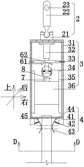
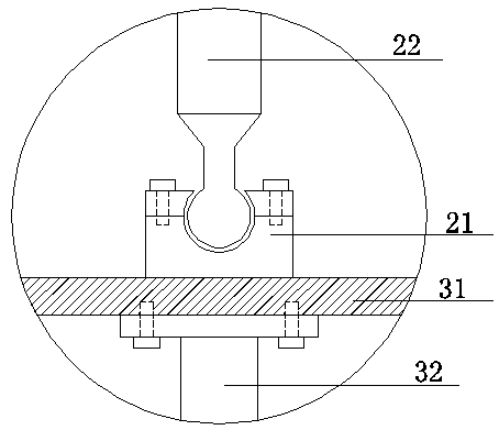
[0049] Embodiment 1: as Figure 1 to Figure 8 The high-strain hammering system for foundation piles shown includes an excavator 1 without a bucket at the end of the forearm, a connecting mechanism 2, a hammering device 3, and a limit mechanism 4. The top of the hammering device 3 passes through the connecting mechanism 2 Hinged to the end of the forearm of the excavator, the bottom is socketed with the pile body 5 through the limit mechanism 4; the connecting mechanism 2 is composed of a connecting seat 21, a connecting rod 22 and a pin shaft 23, and the connecting seat 21 is welded on the hammering device 3 On the top shell 31, one end of the connecting rod 22 is ball-hinged to the connecting seat 21, and the other end is vertically rotatably connected to the end of the forearm of the excavator 1 through the pin A23.

[0050] The hammering device 3 includes a casing 31, a hydraulic jack 32, a limit top plate 33, a decoupling device 34, an energized guide rail 35, and a weight...

Embodiment 2

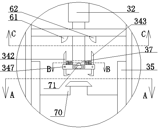
[0059] Embodiment 2: as image 3 As shown, on the front side of the middle block 345, a proximity switch 71 is fixed by a locking bolt to determine whether the top surface of the card table 8 is close to the proximity switch 71 (the distance between the front and back of the top of the card table 8 is greater than the front and rear distance of the middle block 345). When the card platform 8 top surface is close to the proximity switch 71, the energized guide rail 35 is de-energized to prevent the energized guide rail 35 from being energized all the time, so that the weight is always in an accelerated state, and the impact force of the hammer is too fierce; when the card platform 8 leaves the proximity switch 71, that is When the weight 36 falls, the energized guide rail 35 is energized, so that a magnetic field is generated between the two energized guide rails 35, thereby generating a Lorentz force, and applying a downward accelerated Lorentz force to the weight 36 to increas...

Embodiment 3

[0060] Embodiment 3: as Figure 9 to ~ Figure 12 As shown, four support frames 81 are welded in a positive "cross shape" on the side walls around the lower part of the shell 31, and each support frame 81 is fixed with a hydraulic cylinder (82) by bolts. The hydraulic cylinder (82) is inverted and top The direction of the rod is inclined, and the earth shovel (83) is fixed on the ejector rod of the hydraulic cylinder (82). Form a circle, the radius of this circle is greater than or equal to the radius of the pile body 5, the soil around the pile body 5 buried in the ground can be dug out by the soil shovel (83), and then the upper end of the pile body 5 is leaked out, which is convenient for the hammering device The installation of 3 eliminates the need for manual excavation preparations before the test, which is conducive to rapid detection tests and improves work efficiency. At the same time, before digging, the hydraulic cylinder 82 can be used to extend the ejector rod, a...


PUM


Abstract

The invention discloses a foundation pile high-strain hammering system. The foundation pile high-strain hammering system comprises an excavator, a connecting mechanism, a hammering device and a limiting mechanism, wherein the end of the front arm of the excavator does not provide a bucket, the top of the hammering device is hinged to the end of the front arm of the excavator through the connectingmechanism, the bottom of the hammering device is connected with a pile body through the limiting mechanism, the connecting mechanism is composed of a connecting base, a connecting rod and a pin, theconnecting base is welded to an outer shell at the top of the hammering device, one end of the connecting rod is hinged to the connecting base, and the other end of the connecting rod is vertically and rotatably connected to the end of the front arm of the excavator through a pin A. By means of the structure, the hammer device is directly hinged to the end of the front arm of the excavator, so that the hammering device is stable in connection, the problem of slipping accidents is not prone to happening, and the safety is high; meanwhile, the hammering device and a foundation pile end head arebutted in real time through the limiting mechanism, the installation is simple, and the operation efficiency is greatly improved.

Description

technical field [0001] The invention relates to the field of foundation pile detection, in particular to a foundation pile high strain hammering system. Background technique [0002] The high strain method uses a heavy hammer to impact the top of the pile, and measures the force and velocity time history curves at the top of the pile. Through wave theory analysis, the vertical compressive bearing capacity of the single pile and the integrity of the pile body are analyzed through wave theory. The vertical compressive bearing capacity and the integrity of the pile body are judged. At present, there are two ways to load the existing high-strain hammering device: one is when the site conditions are average, such as when the land surface is relatively flat, it is loaded by a crane; the other is when the site conditions are poor, such as the ground surface is uneven, When the drop is relatively obvious, the crane cannot enter, and the test is difficult, so it is loaded by hanging...

Claims


Application Information

Patent Timeline
Patent Type & Authority Applications(China)
IPC IPC(8): E02D33/00E02D5/22
CPCE02D5/22E02D33/00
Inventor 李东昌樊勇王鹏鹿逢月陈慧
Owner 淮安市建筑工程质量检测中心有限公司
Why Eureka
Try Eureka