Portable antiskid luggage case

A suitcase and portable technology, applied in the field of suitcases, can solve the problems of occupying space, multiple structures, and large size, etc., and achieve the effects of easy operation, simple and efficient transmission, and simple structure

Pending Publication Date: 2020-07-10
屠西理
View PDF0 Cites 3 Cited by
  • Summary
  • Abstract
  • Description
  • Claims
  • Application Information

AI Technical Summary

Problems solved by technology

However, there are more and more problems that suitcases tend to slip sideways. On buses, subways, slopes, etc. where there is a tendency to move, or when we need to scan the code to pay, or make calls, the suitcase will be supervised. If the suitcase is lost, it is easy to injure others when the suitcase moves, or the suitcase may be injured and damaged, causing inconvenience
[0003] Currently on the market, the anti-skid mechanism of the anti-skid suitcase is not convenient enough for anti-skid operation. It has many structures and a large body, which takes up space in the box and affects the original moving function of the suitcase.

Method used


Image

  • Portable antiskid luggage case
  • Portable antiskid luggage case
  • Portable antiskid luggage case

Examples


Embodiment 1

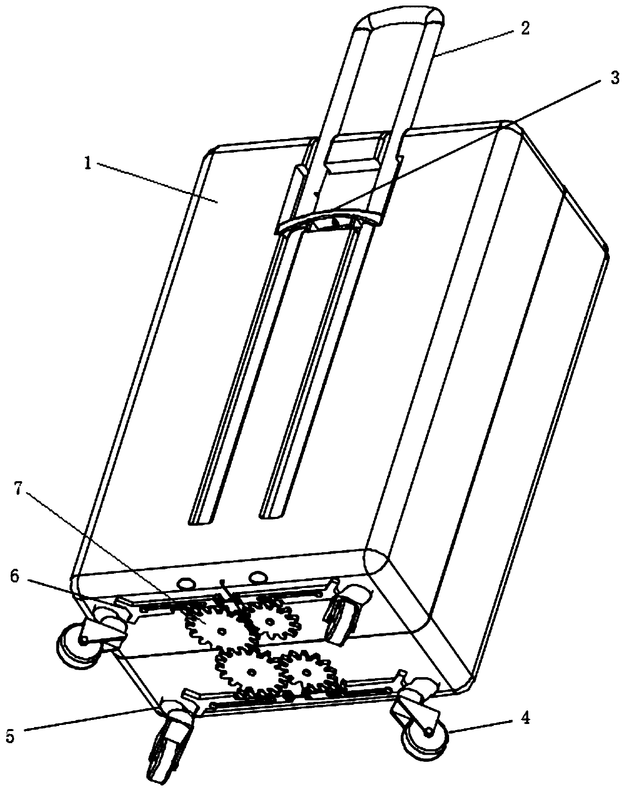
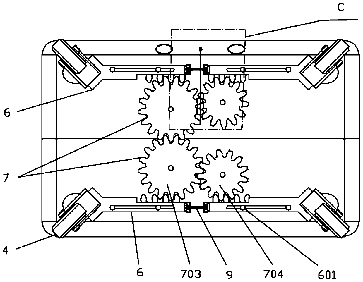
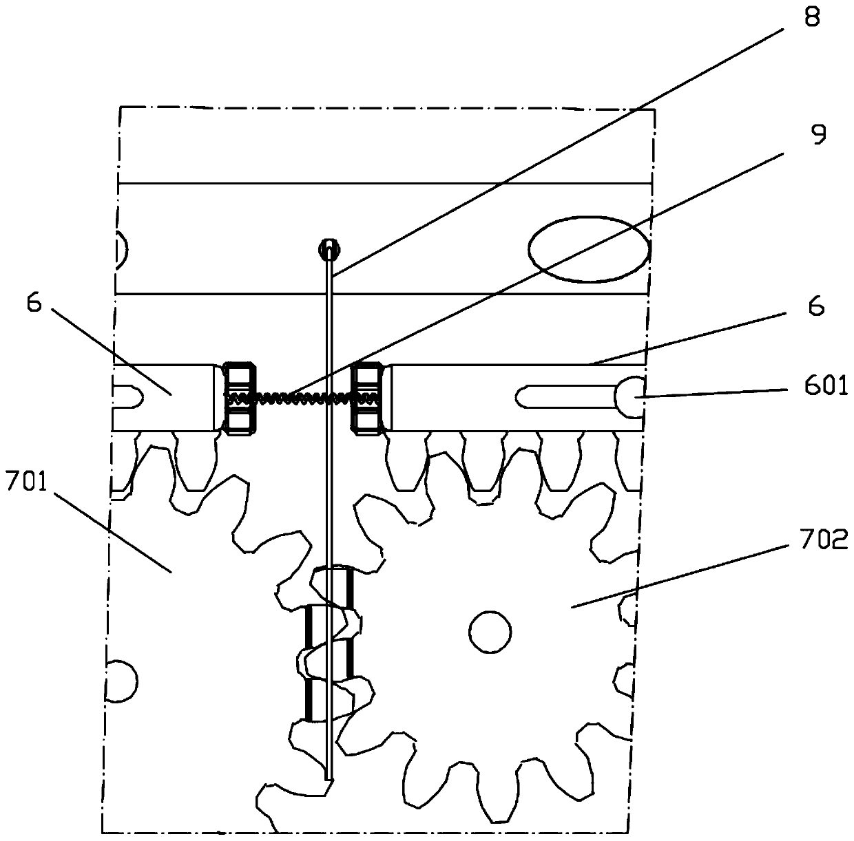
[0032] see Figure 1-8 , in an embodiment of the present invention, a portable non-slip luggage case includes a case body 1 and a pull rod 2, the pull rod 2 is installed on the case body 1, and also includes an anti-slip device, and the anti-slip device includes a driving member, a transmission member and a locking member, the driving member is movably installed on the pull rod 2, the transmission member connects the driving member and the locking member, a moving member is installed on the bottom of the box body 1, and the driving member The locking part is driven by the transmission part to move, and the moving locking part interferes with the stroke of the moving part.

[0033] Specifically, the locking part is movably installed on the side of the moving part, and is in intermittent contact with the moving part. Under normal conditions, the locking part does not contact the moving part, and the box can be freely moved The pull rod 2 is pulled. When anti-skidding is requir...

Embodiment 2

[0051] see Figure 9-12 , in order to cope with heavy load scenarios, in another embodiment provided by the present invention, the transmission member is a link mechanism, and the link mechanism includes a link 10, a limit block 13 and a connecting rod 12, and several of the link Rod 10 is hinged to form a link mechanism, and the link mechanism is connected with the driving member. The limit block 13 supports the link mechanism, and the two ends of the link mechanism are connected to each other by the connecting rod 12. The lock is connected.

[0052] Specifically, the four connecting rods 10 are hinged to form a quadrilateral connecting rod structure, and a hinged hole of the connecting rod 10 away from the pull rod is connected with a return spring 11, and is also connected to one end of the steel wire rope 8; the quadrilateral connecting rod mechanism The two ends of the connecting rod 10 are connected to the connecting rod 12, the quadrilateral connecting rod structure is...


PUM


Abstract

The invention relates to a luggage case, in particular to a portable antiskid luggage case comprising a box body and a pull rod. The pull rod is mounted on the box body; an anti-skid device is furtherincluded, the anti-skid device comprises a driving piece, a transmission piece and a locking piece. The driving piece is movably installed on the pull rod, and the transmission piece is connected with the driving piece and the locking piece; a moving piece is installed at the bottom of the box body; the driving piece drives the locking piece to move through the transmission piece; and the moved locking piece interferes with the stroke of the moving piece. The anti-skid luggage case has the advantages that the operation position is arranged on the pull rod, the antiskid luggage case conforms to the operation position when a human body stands upright and is easy to operate; the antiskid luggage case is simple in structure and easy and efficient in transmission; the whole structure is hiddenat the bottom of the box body, and extra space of the box body is not occupied.

Description

technical field [0001] The invention relates to a suitcase, in particular to a portable non-slip suitcase. Background technique [0002] Suitcase is an essential tool for business travel. Today, travel is more convenient, and travel is becoming more and more common. Suitcases are used more and more frequently. However, there are more and more problems that suitcases tend to slip sideways. On buses, subways, slopes, etc. where there is a tendency to move, or when we need to scan the code to pay, or make calls, the suitcase will be supervised. If the suitcase is lost, it is easy to injure others when the suitcase moves, or the suitcase may be injured or damaged, causing inconvenience. [0003] Currently on the market, the anti-skid mechanism of the anti-skid suitcase is not convenient enough for the anti-skid operation. It has many structures, is large in size, takes up space in the box body, and also affects the original moving function of the suitcase. Contents of the inv...

Claims


Application Information

Patent Timeline
Patent Type & Authority Applications(China)
IPC IPC(8): A45C5/04A45C5/14A45C13/00
CPCA45C5/045A45C5/14A45C13/00
Inventor 屠西理
Owner 屠西理
Why Eureka
Try Eureka