Punching blanking die

Active Publication Date: 2020-07-10
佛山真明叶电器有限公司
View PDF10 Cites 3 Cited by
  • Summary
  • Abstract
  • Description
  • Claims
  • Application Information

AI Technical Summary

Problems solved by technology

[0003] During the processing of the punching and blanking die, since the stamped parts fall into the groove of the die and fit closely with the inner wall of the die groove, when the whole part is tilted during the removal process, it is easy to cause the parts to be stuck in the die The situation in the groove, so that the processing process is affected to a certain extent

Method used


Image

  • Punching blanking die
  • Punching blanking die
  • Punching blanking die

Examples


Embodiment 1

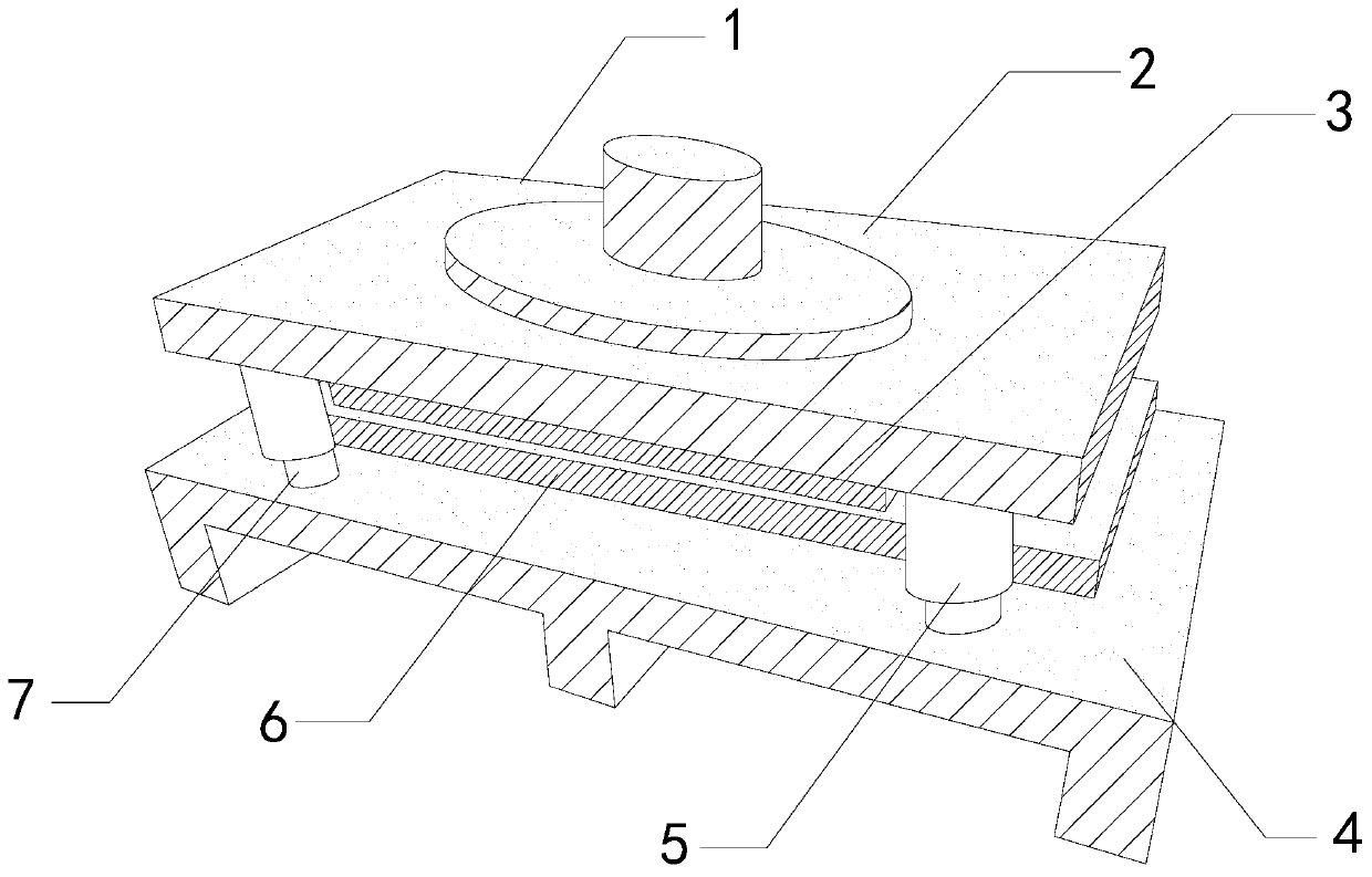
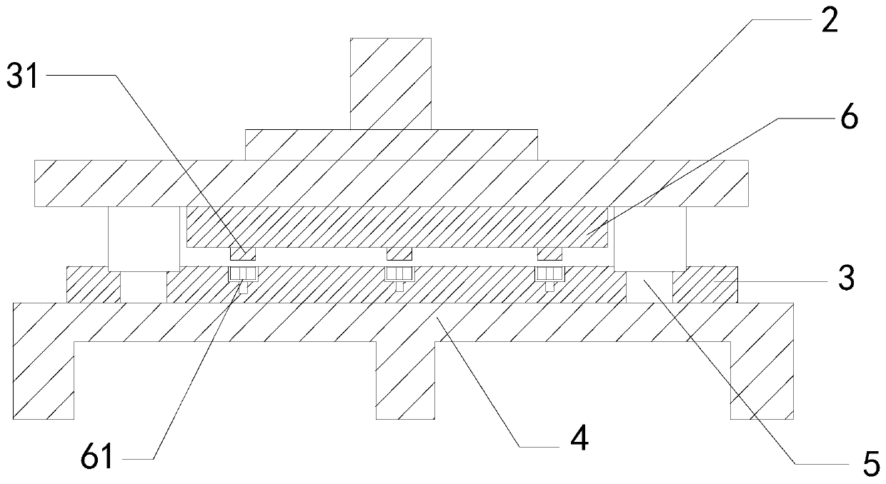
[0027] As for example figure 1 -example Image 6 Shown:

[0028] The present invention provides a punching and blanking die, the structure of which includes a die 1, an upper die seat 2, a convex template 3, a base 4, a guide sleeve 5, a concave template 6, a guide post 7, a punching convex die 31, and a concave die groove 61, The upper mold base 2 is fixed to the upper end position of the mold 1, the convex template 3 is fixedly connected to the upper mold base 2, the base 4 is fixed to the lower end position of the mold 1, and the guide sleeve 5 and the upper mold base 2 Embedded connection, the concave template 6 is embedded and connected with the base 4, one end of the guide post 7 is in clearance fit with the guide sleeve 5, the other end of the guide post 7 is embedded and connected with the base 4, the punching punch 31 is provided with three embedding connections with the male template 3, and three female mold grooves 61 are provided on the female template 6.

[0029] The ...

Embodiment 2

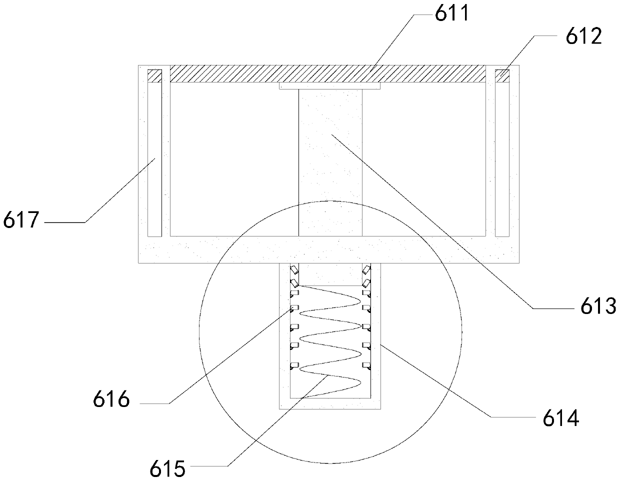
[0035] As for example Figure 7 -example Picture 9 Shown:

[0036] Among them, the rebound device a1 is mainly composed of a reset spring a11, a movable rod a12, and a blocking block a13. The reset spring a11 is fixed to the outer position of the movable rod a12, and one end of the movable rod a12 is embedded in the inner wall of the catheter 614. The other end of the movable rod a12 is in clearance fit with the movable block a2, the blocking block a13 is embedded and fixedly connected with the movable rod a12, and the movable rod a12 is of an arc structure, so as to move with the movable block a2. The trajectory fits well.

[0037] Wherein, the front end of the rubber block a3 is provided with rubber bumps a31, the rubber bumps are provided with thirty-six, and are evenly distributed on the front end surface of the rubber block a3, which can strengthen the surface of the rubber block a3 and the lifting rod 613 The friction force improves the cushioning effect of the cushioning ...


PUM


Abstract

The invention discloses a punching blanking die. The punching blanking die structurally includes a die, an upper die seat, a convex die plate, a base, a guide sleeve, a concave die plate, a guide pillar, a punching convex die, and concave die grooves. The upper die seat is fixed to the upper end of the die, the convex die plate is fixedly connected with the upper die seat in an embedded mode, thebase is fixed to the lower end of the die, and three concave die grooves are formed in the concave die plate. When a material on the concave die plate is machined by the punching convex die on the convex die plate, the pressure is applied to a lifting plate through the punching convex die, so that the parts separated from the material fall into the concave die grooves, and a round roller on a movable block is attached to the surface of a lifting rod, so that the lifting rod is more stable when the lifting rod is lowered. After machining is finished, upward force is transmitted through a springin a guide tube to enable the lifting rod to rise upwards again, so that a lifting plate connected with the lifting rod drives the parts to rise upwards, and the rising speed of the lifting rod can be slowed down by a rubber block on a buffer mechanism.

Description

Technical field [0001] The invention relates to the field of moulds, in particular to a punching and blanking mould. Background technique [0002] The punching and blanking die is a pressure processing method that uses the die on the pressure device to apply pressure to the material to separate the parts from the material, thereby obtaining the required parts. The punching and blanking die can be used for punching, blanking, Based on the above description, the inventor found that the current punching and blanking die mainly has the following deficiencies, such as bending and deep drawing and other forming processes, such as: [0003] During the processing of the punching and blanking die, since the stamped parts fall into the cavity of the cavity and closely fit the inner wall of the cavity, when the entire part is tilted during the removal process, it is easy to cause the parts to be stuck in the cavity The situation in the groove will affect the machining process to a certain ex...

Claims


Application Information

Patent Timeline
IPC IPC(8): B21D28/14B21D28/34B21D37/12
CPCB21D28/14B21D28/34B21D37/12
Inventor 闫华耀
Owner 佛山真明叶电器有限公司
Why Eureka
Try Eureka