
Tool for high-speed numerical control milling machining of thin-walled part

A technology for CNC milling and thin-walled parts, which is applied to metal processing equipment, metal processing mechanical parts, positioning devices, etc., and can solve the problems affecting the dimensional accuracy and shape accuracy of thin-walled parts, clamping deformation of thin-walled parts, and inconvenience in use. , to achieve the effect of improving processing quality, avoiding clamping deformation and wide application range

Inactive Publication Date: 2020-07-10
HUNAN IND POLYTECHNIC
View PDF9 Cites 3 Cited by
  • Summary
  • Abstract
  • Description
  • Claims
  • Application Information

AI Technical Summary

Problems solved by technology

[0002] Thin-walled parts have the characteristics of light weight, material saving, and compact structure. However, due to poor rigidity and weak strength, thin-walled parts are easily deformed during CNC milling, which increases the shape and position error of thin-walled parts, and it is difficult to ensure thin-walled parts. The processing quality of thin-walled parts, and the existing tooling for thin-walled parts clamping adopts a rigid clamping method, which is easy to cause clamping deformation of thin-walled parts, which affects the dimensional accuracy and shape accuracy of thin-walled parts, thereby affecting thin-walled parts. The processing quality of the parts, at the same time, the existing tooling can only be used for the clamping of a single thin-walled part, which has a single function and is inconvenient to use

Method used


Image

  • Tool for high-speed numerical control milling machining of thin-walled part
  • Tool for high-speed numerical control milling machining of thin-walled part
  • Tool for high-speed numerical control milling machining of thin-walled part

Examples


Embodiment Construction

[0030] In order to enable those skilled in the art to better understand the technical solution of the present invention, the present invention will be described in detail below in conjunction with the accompanying drawings. The description in this part is only exemplary and explanatory, and should not have any limiting effect on the protection scope of the present invention. .

[0031] It should be noted that like numerals and letters denote similar items in the following figures, therefore, once an item is defined in one figure, it does not require further definition and explanation in subsequent figures.

[0032] It should be noted that the orientation or positional relationship indicated by the terms "center", "upper", "lower", "left", "right", "vertical", "horizontal", "inner" and "outer" are Based on the orientation or positional relationship shown in the drawings, or the orientation or positional relationship that the inventive product is usually placed in use, it is onl...


PUM


Abstract

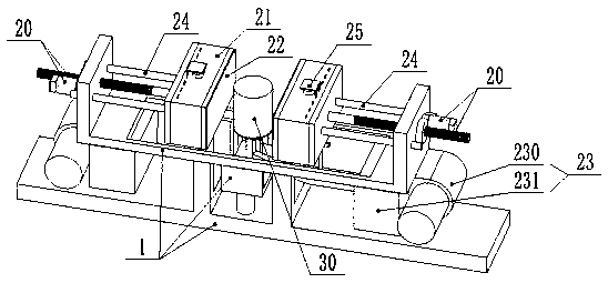
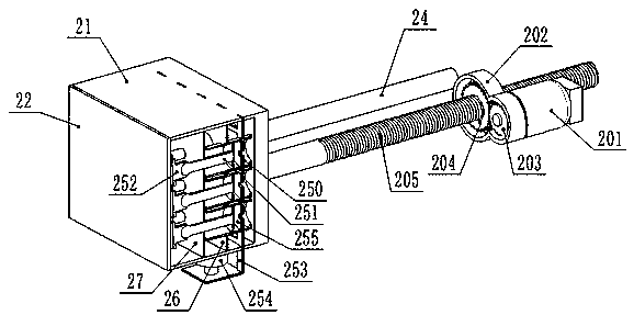
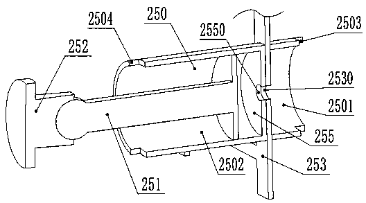
The invention discloses a tool for high-speed numerical control milling machining of a thin-walled part. The tool comprises a support, a support and two follow-up clamping devices oppositely arrangedon the support, wherein each follow-up clamping device comprises a first linear driving mechanism, a hollow shell, a heating mechanism, a gas supply mechanism, a deformation mechanism and a floating clamp, each deformation mechanism comprises a planar thermoplastic layer and an elastic outer layer wrapping the planar thermoplastic layer, and each floating clamp comprises cylinder bodies, floatingchucks, pistons, a second linear driving mechanism and a closed partition plate. According to the tool, the flexible clamping of the thin-walled part is realized, the thin-walled part can be effectively attached, the clamping deformation of the thin-walled part is effectively avoided, the machining quality of the thin-walled part is improved, clamping of different thin-wall parts can be realized,and the application range is wide.

Description

technical field [0001] The invention relates to the technical field of machining fixtures, in particular to a tooling for high-speed numerical control milling of thin-walled parts. Background technique [0002] Thin-walled parts have the characteristics of light weight, material saving, and compact structure. However, due to poor rigidity and weak strength, thin-walled parts are easily deformed during CNC milling, which increases the shape and position error of thin-walled parts, and it is difficult to ensure thin-walled parts. The processing quality of thin-walled parts, and the existing tooling for thin-walled parts clamping adopts a rigid clamping method, which is easy to cause clamping deformation of thin-walled parts, which affects the dimensional accuracy and shape accuracy of thin-walled parts, thereby affecting thin-walled parts. The processing quality of the parts, while the existing tooling can only be used for the clamping of a single thin-walled part, has a singl...

Claims


Application Information

Patent Timeline
Patent Type & Authority Applications(China)
IPC IPC(8): B23Q3/08
CPCB23Q3/08B23Q3/086
Inventor 刘瑞已
Owner HUNAN IND POLYTECHNIC
Learn More