
A vibrating device for prefabricated concrete

A prefabricated component and concrete technology, which is applied in manufacturing tools, ceramic molding machines, auxiliary molding equipment, etc., can solve the problems affecting the pouring quality of subsequent prefabricated concrete components, the degree of compaction of prefabricated concrete components, and the poor mixing effect of concrete, etc. problems, to achieve the effect of improving pouring quality, uniform compaction, and improving mixing effect

Active Publication Date: 2021-05-18
广东鑫隆管业有限公司
View PDF7 Cites 0 Cited by
  • Summary
  • Abstract
  • Description
  • Claims
  • Application Information

AI Technical Summary

Problems solved by technology

[0003] The purpose of the present invention is to provide a vibrating device for concrete prefabricated components to solve the problem of poor concrete mixing effect in the prior art, which affects the pouring quality of subsequent concrete prefabricated components, and the artificial labor intensity, low work efficiency, and easy occurrence of concrete prefabrication Technical problems that occur in the case of uneven compaction of components

Method used


Image

  • A vibrating device for prefabricated concrete
  • A vibrating device for prefabricated concrete
  • A vibrating device for prefabricated concrete

Examples


Embodiment Construction

[0025] In order to make the object, technical solution and advantages of the present invention clearer, the present invention will be further described in detail below in conjunction with the accompanying drawings and embodiments. It should be understood that the specific embodiments described here are only used to explain the present invention, not to limit the present invention.

[0026] In describing the present invention, it should be understood that the terms "longitudinal", "transverse", "upper", "lower", "front", "rear", "left", "right", "vertical", The orientations or positional relationships indicated by "horizontal", "top", "bottom", "inner", "outer", etc. are based on the orientations or positional relationships shown in the drawings, and are only for the convenience of describing the present invention, rather than indicating or It should not be construed as limiting the invention by implying that a referenced device or element must have a particular orientation, be...


PUM


Abstract

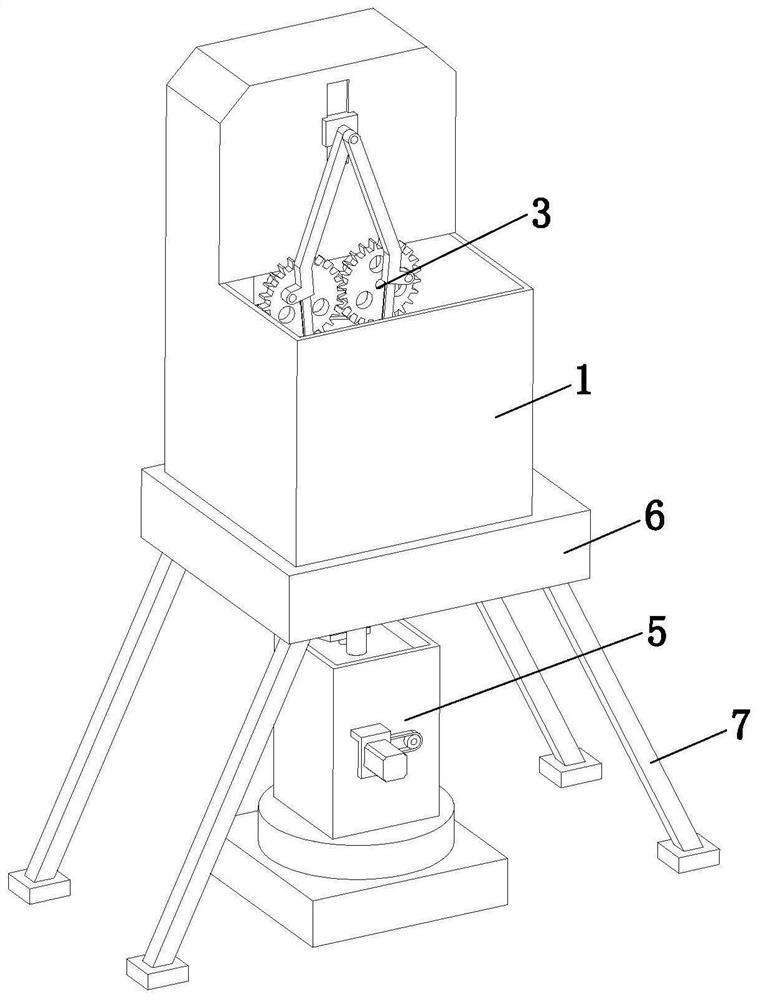
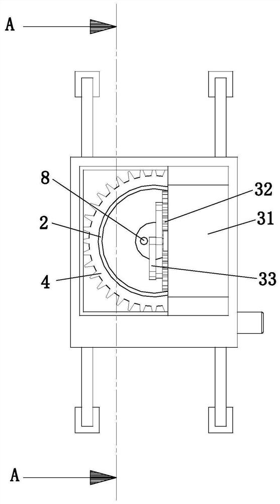
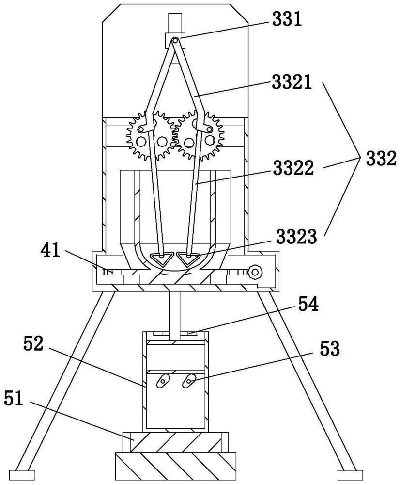
The invention relates to the field of building construction equipment, and discloses a vibrating device for prefabricated concrete components, which includes a material receiving box, a material loading bucket, an agitating mechanism, a material discharging mechanism and a compacting mechanism. Connected bottom box, the bottom of the bottom box is provided with a supporting bracket fixedly connected with it, the loading barrel is fixed on the discharge mechanism, the discharge mechanism is installed in the bottom box, and the stirring mechanism is installed on the inner top of the material receiving box , the bottom of the loading barrel is provided with a discharge port, the bottom of the bottom box is provided with a discharge channel that communicates with the discharge port, and the compacting mechanism is arranged below the bottom case and connected to the bottom of the discharge channel , the invention improves the mixing effect of concrete raw materials in the loading tank and the pouring quality of subsequent concrete prefabricated components, and can realize automatic compaction of concrete, and the degree of compaction is uniform, which solves the problem of traditional manual beating of concrete problems and improve work efficiency.

Description

technical field [0001] The invention relates to the field of building construction equipment, in particular to a vibrating device for concrete prefabricated components. Background technique [0002] Concrete prefabricated components are called PC components in the field of residential industrialization. Such as prefabricated reinforced concrete column foundation, prefabricated steel structure steel column foundation, street lamp billboard column reinforced concrete foundation, prefabricated floor slab. Correspondingly, traditional cast-in-place concrete requires on-site molding, on-site pouring and on-site maintenance. Prefabricated concrete is widely used in construction, transportation, water conservancy and other fields. At present, when pouring concrete prefabricated components, the existing concrete mixer is usually used to mix the concrete. However, when the existing concrete mixer mixes the concrete, the mixing track is single, which easily makes the concrete mixing...

Claims


Application Information

Patent Timeline
Patent Type & Authority Patents(China)
IPC IPC(8): B28B1/08B28B3/02B28B17/02B28B17/00
CPCB28B3/022B28B17/00B28B17/02
Inventor 肖煜唐雪峰
Owner 广东鑫隆管业有限公司
Learn More