Varnish printing device for UV printer

A printing device and printer technology, applied in printing, non-electric variable control, instruments, etc., can solve the problems that the viscosity cannot reach the design viscosity, the printing nozzle consumes manpower, unfavorable UV varnish leveling and rapid curing, etc., to achieve good printing effect of effect

Pending Publication Date: 2020-07-10
珠海炫彩科技有限公司
View PDF0 Cites 0 Cited by
  • Summary
  • Abstract
  • Description
  • Claims
  • Application Information

AI Technical Summary

Problems solved by technology

[0004] During the printing process, when the ink ejection volume of the print head is large, if it is not cleaned in time, the remaining large amount of ink is very easy to solidify, which is likely to have a negative impact on the next printing, but frequent cleaning of the print head is extremely labor-intensive
At the same time, during the printing process of the UV printer, if the ambient temperature is low, its viscosity will not reach the design viscosity, which is not conducive to the leveling and rapid curing of UV varnish. Therefore, we propose a UV varnish for UV printer. oil printing device

Method used


Image

  • Varnish printing device for UV printer
  • Varnish printing device for UV printer
  • Varnish printing device for UV printer

Examples


Embodiment 1

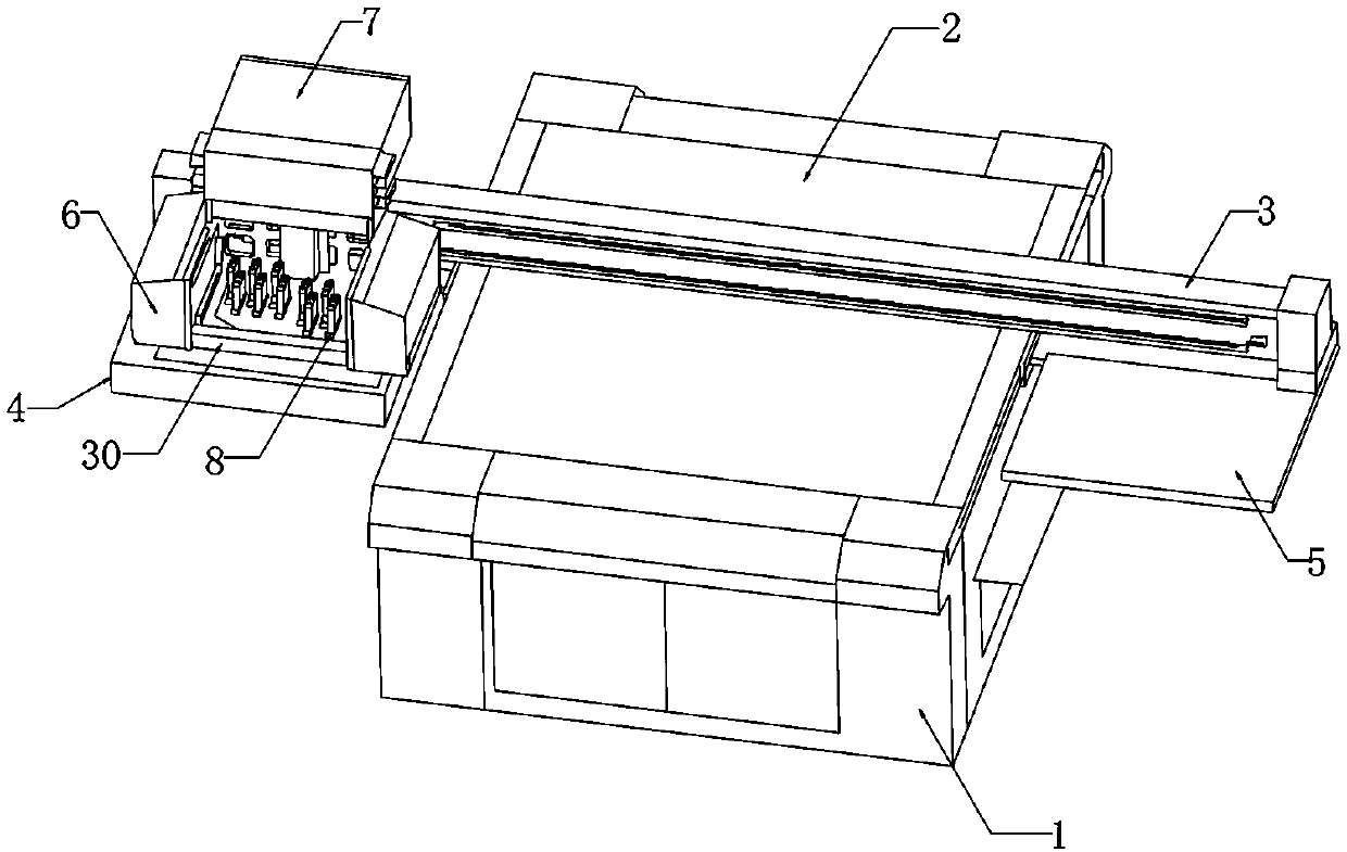
[0027] Such as Figure 1-4 As shown, a varnish printing device for UV printers includes a frame (1), a cleaning table (4) and an installation box (7). A workbench (2) is installed on the top of the frame (1). A cleaning table (4) is installed on one side of the frame (1), a support plate (5) is installed on the other side of the frame (1), and a guide rail (3) is connected to one side of the cleaning table (4), and the guide rail (3 ) is slidingly connected to one side of the mounting box (7).

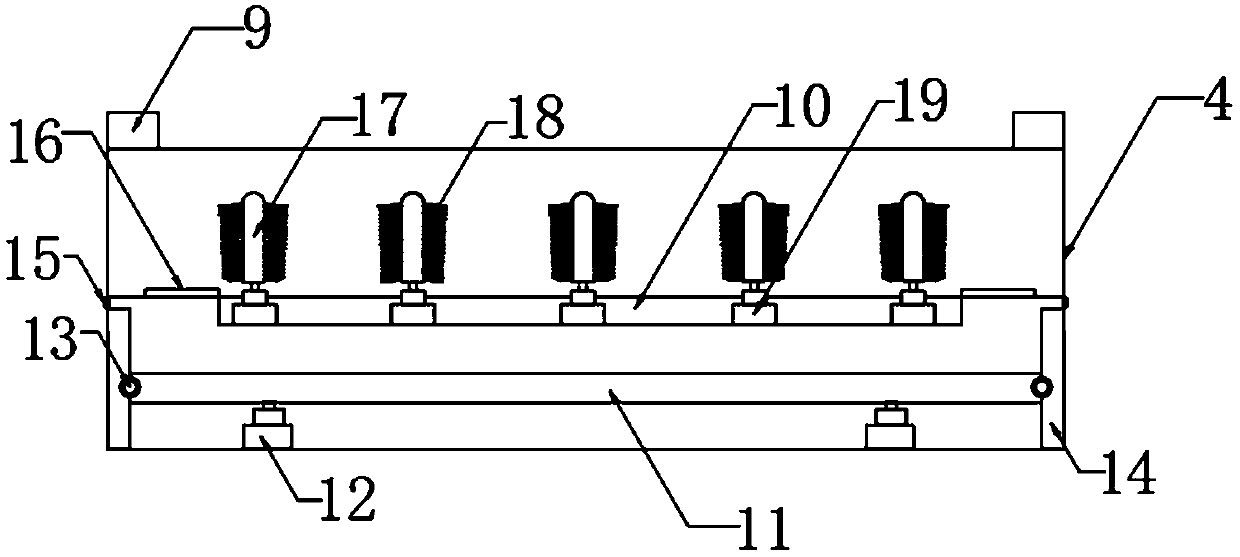
[0028] Limiting blocks (9) are installed on both sides of the top of the cleaning table (4), the middle of the cleaning table (4) is fixed with a mounting plate (10), and filter plates (16) are installed on both sides of the mounting plate (10). The interior of the mounting plate (10) is fixedly installed with several first rotating motors (19), and the rotating shaft of each first rotating motor (19) is fixedly installed with a fixed column (17), and each fixed column (17) The surfa...

Embodiment 2

[0033] Such as Figure 1-4 As shown, a varnish printing device for UV printers includes a frame (1), a cleaning table (4) and an installation box (7). A workbench (2) is installed on the top of the frame (1). A cleaning table (4) is installed on one side of the frame (1), a support plate (5) is installed on the other side of the frame (1), and a guide rail (3) is connected to one side of the cleaning table (4), and the guide rail (3 ) is slidingly connected to one side of the mounting box (7).

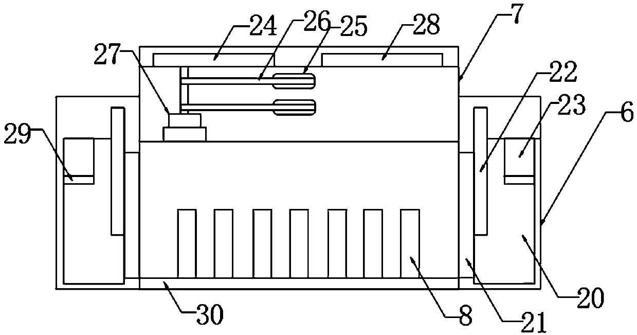
[0034] Both sides of the bottom of the installation box (7) are fixedly installed with a fixed box (6), and one side inside each fixed box (6) is fixedly installed with an air storage box (20), and each inner side of the air storage box (20) Fans (23) are fixedly installed on the top of each fan (23), and heating pipes (29) are fixedly installed at the bottom of each fan (23), and the other side of each air storage box (20) is fixedly equipped with an air guide port (21) , a gate val...

Embodiment 3

[0039] Such as Figure 1-4 As shown, a varnish printing device for UV printers includes a frame (1), a cleaning table (4) and an installation box (7). A workbench (2) is installed on the top of the frame (1). A cleaning table (4) is installed on one side of the frame (1), a support plate (5) is installed on the other side of the frame (1), and a guide rail (3) is connected to one side of the cleaning table (4), and the guide rail (3 ) is slidingly connected to one side of the mounting box (7).

[0040] The two sides of the top of installation box (7) are installed with circuit board (24) and controller (28) respectively, and circuit board (24) is electrically connected with heating tube (29), and controller (28) is respectively connected with guide rail (3 ), varnish printing nozzle (8), push rod motor (12), first rotating motor (19), second rotating motor (27), water valve (15), gate valve (22) and fan (23) Electrically connected, the controller (28) is connected to it thro...


PUM


Abstract

The invention discloses a varnish printing device for a UV printer. The varnish printing device for the UV printer comprises a rack, a cleaning table and a mounting box; a workbench is installed at the top end of the rack; the cleaning table is installed on one side of the rack; a supporting plate is installed on the other side of the rack; a guide rail is connected to one side of the cleaning table; and the mounting box is in sliding connection with one side of the guide rail. According to the varnish printing device for the UV printer, due to the arranged cleaning table, a varnish printing spray head can be cleaned, and the phenomenon that after the UV printer works, lots of remaining printing ink is difficult to clean out is avoided; due to the arrangement of an air storing box, a draught fan and a heating pipe, UV varnish can be subjected to fast levelling and solidifying when a temperature is low, so that varnish on the varnish printing spray head has a better printing effect; anddue to a temperature control circuit on an arranged circuit board, the heating pipe can provide a balanced and continuous heat flow, and influences caused by nonuniform heat on the varnish are avoided.

Description

technical field [0001] The invention relates to the field of UV printers, in particular to a varnish printing device for UV printers. Background technique [0002] UV printer is a high-tech plate-free full-color digital printing machine. It is not limited by materials. It can print on T-shirts, sliding doors, cabinet doors, sliding doors, glass, plates, various signs, crystal, PVC, acrylic, metal , plastic, stone, leather and other surfaces for color photo-level printing, the difference between it and traditional inkjet printing is that it has UV ink and UV lamp on the equipment, which uses the components in the UV ink to produce under the irradiation of specific wavelengths of ultraviolet light The cross-linking polymerization reaction speeds up the film formation of the ink, achieves its immediate drying and sampling immediately, and solves the problem of not using white ink with color ink, forming a unique artistic style. The printed pattern is not only full of concave a...

Claims


Application Information

Patent Timeline
IPC IPC(8): B41J2/165B41J2/135G05D23/24
CPCB41J2/135B41J2/16552B41J2002/16558G05D23/24
Inventor 郑才博杨春帆
Owner 珠海炫彩科技有限公司
Why Eureka
Try Eureka