Al technical title is built by PatSnap Al team. It summarizes the technical point description of the patent document.
A technology of trash cans and outer barrels, applied in trash cans, garbage collection, water conservancy projects, etc., can solve problems such as landscape deterioration, water quality deterioration, river pollution, etc., and achieve reduced labor intensity, reduced treatment costs, and a wide range of applications Effect
Inactive Publication Date: 2020-07-10
SHANXI SHANGFENG TECH
View PDF7 Cites 7 Cited by
Summary
Abstract
Description
Claims
Application Information
AI Technical Summary
This helps you quickly interpret patents by identifying the three key elements:
Problems solved by technology
Method used
Benefits of technology
Problems solved by technology
[0002] At present, due to man-made or natural reasons in many waters, most scenic spots have lakes, ponds, and waterways, or there are a lot of floating garbage in places close to rivers or seaside. The most surface garbage is plastic products, branches and leaves, etc. , the existence of a large amount of garbage will lead to the deterioration of the landscape, the pollution of the river, and the deterioration of the water quality
However, most of the garbage on the water surface is manually salvaged, which is time-consuming, labor-intensive, costly and has certain operational risks.
With the rapid development of science and technology, trash cans have also been improved technically, but the existing technology of collecting garbage on water requires power supply from the shore, which has limitations on the self-collection of garbage on the water surface, and can only ensure that the water surface on the shore is clean
Method used
Image
Click on the blue label to locate the original text in one second.
Reading with bidirectional positioning of images and text.
Examples
Embodiment Construction
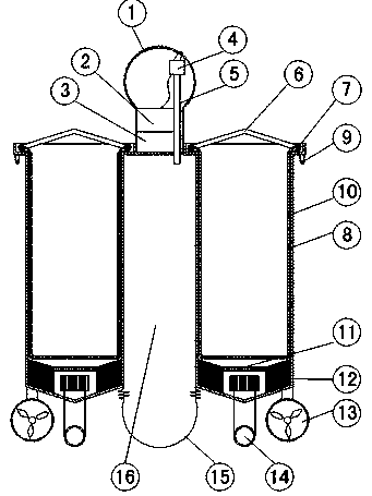
[0030] figure 1 , figure 2 Shown, a kind of trash can on water is made up of solar ball 1, PLC2, accumulator 3, air pump 4, air pipe 5, water flow generator 13, water pump 14, air bag 15, hollow pipe 16, four trash cans.
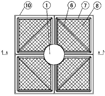
[0031] The four trash cans are placed in pairs to form a square column. A hollow tube sits in the center of the four bins.
[0032] A PLC2 and a storage battery 3 are arranged on the top of the hollow tube 16, and a solar ball 1 is arranged on the PLC2.
[0033] The PLC2 is connected to the air pump 4, and the air pump 4 is connected to the air pipe 5. The trachea 5 extends into the inner cavity of the hollow tube, and the lower part of the hollow tube 16 is connected with the air bag 15 .
[0034] Garbage can is made up of lifting rod 6, inner bucket ring 7, inner bucket 8, water level sensor 9, outer bucket 10, filter screen 11, counterweight 12.
[0035] The outer barrel 10 is set outside the inner barrel 8, the top of the inner barrel 8 is provided...
PUM
Abstract
The invention discloses an on-water garbage can, and relates to the field of environment friendliness. The on-water garbage can comprises a solar energy ball, a PLC, a storage battery, an air pump, anair pipe, a water flow electric generator, a water suction pump, an air bag, a hollow pipe and four garbage can bodies, the four garbage can bodies depend on each other in pairs to form a cylinder, the hollow pipe is located in the centers of the four garbage can bodies, the PLC and the storage battery are mounted on the top of the hollow pipe, the solar energy ball is mounted on the PLC, the PLCis connected with the air pump, the air pump is connected with the air pipe, the air pipe extends into an inner cavity of the hollow pipe, and the lower portion of the hollow pipe is connected with the air bag. The garbage can can float on the water surface, floating garbage in the water can be collected, along with continuously-increased collected garbage, gravity is increased, a water level sensor detects that data are sent back to the PLC, the air pump is controlled to be started, the air bag is inflated, buoyancy is increased, a cornice of the garbage can can be kept under the water by 1to 3 cm until the can is full of the collected garbage, a worker can clean the garbage in time, the on-water garbage can be cleaned without ship arrangement, labor intensity is reduced, and treatmentcost is reduced.
Description
technical field [0001] The invention relates to the field of environmental protection, in particular to a water trash can. Background technique [0002] At present, due to man-made or natural reasons in many waters, most scenic spots have lakes, ponds, and waterways, or there are a lot of floating garbage in places close to rivers or seaside. The most surface garbage is plastic products, branches and leaves, etc. , the existence of a large amount of garbage will lead to the deterioration of the landscape, the pollution of the river, and the deterioration of the water quality. However, most of the garbage on the water surface is manually salvaged, which is time-consuming, labor-intensive, costly and has certain operational risks. With the rapid development of science and technology, trash cans have also been technically improved. However, the existing water garbage collection technology requires shore power supply, which has limitations on the self-collection of water surfac...
Claims
Application Information
Patent Timeline
Application Date:The date an application was filed.
Publication Date:The date a patent or application was officially published.
First Publication Date:The earliest publication date of a patent with the same application number.
Issue Date:Publication date of the patent grant document.
PCT Entry Date:The Entry date of PCT National Phase.
Estimated Expiry Date:The statutory expiry date of a patent right according to the Patent Law, and it is the longest term of protection that the patent right can achieve without the termination of the patent right due to other reasons(Term extension factor has been taken into account ).
Invalid Date:Actual expiry date is based on effective date or publication date of legal transaction data of invalid patent.