An anti-collision support structure for dock lifting equipment

A lifting equipment and support structure technology, which is applied to the bottom support structure, crane, mechanical equipment, etc., can solve the problems of buffering, guiding and fixing of the anti-collision structure, affecting the stability of the lifting equipment, and large shaking of the lifting equipment. The effect of reducing shaking, avoiding damage, and good protective treatment

Active Publication Date: 2021-12-28
东台永胜盈华游艇有限公司
View PDF8 Cites 0 Cited by
  • Summary
  • Abstract
  • Description
  • Claims
  • Application Information

AI Technical Summary

Problems solved by technology

[0005] Aiming at the deficiencies in the prior art, the present invention provides an anti-collision support structure for dock lifting equipment, which ensures that the body of the lifting equipment is protected due to swing during the process of hoisting and transporting goods, and can better protect the lifting equipment. The heavy equipment is protected to avoid damage to the lifting equipment during the lifting of the cargo, which improves the stability of the lifting equipment during use, and can better fix the buffer guide of the anti-collision structure and weaken the lifting force. The shaking of the equipment during the buffering process ensures that the goods can be lifted normally, ensures that the protective treatment of the goods is in a better condition, and avoids damage to the goods due to impact. In the use of lifting equipment, due to lifting When the damage of the equipment needs to be maintained, it is convenient for the staff to carry out safety protection, and the progress of the maintenance of the lifting equipment is improved. The main body causes impact, and it is necessary to use the anti-collision support structure to protect the lifting equipment for lifting goods, which may cause damage to the lifting equipment during the lifting process, thereby affecting the stability of the lifting equipment, and cannot be well protected against The buffer guide of the collision structure is fixed, so that the overall shaking of the lifting equipment during the buffer process becomes larger and larger, which affects the normal lifting of the cargo. Nowadays, in the process of buffering and anti-collision of the cargo, it is necessary to protect the cargo, which may be due to Damage to the goods caused by impact. During the use of the lifting equipment, when maintenance is required due to the damage of the lifting equipment, the safety protection of the staff cannot be well protected, which affects the progress of the maintenance of the lifting equipment.

Method used


Image

  • An anti-collision support structure for dock lifting equipment
  • An anti-collision support structure for dock lifting equipment
  • An anti-collision support structure for dock lifting equipment

Examples


Embodiment 1

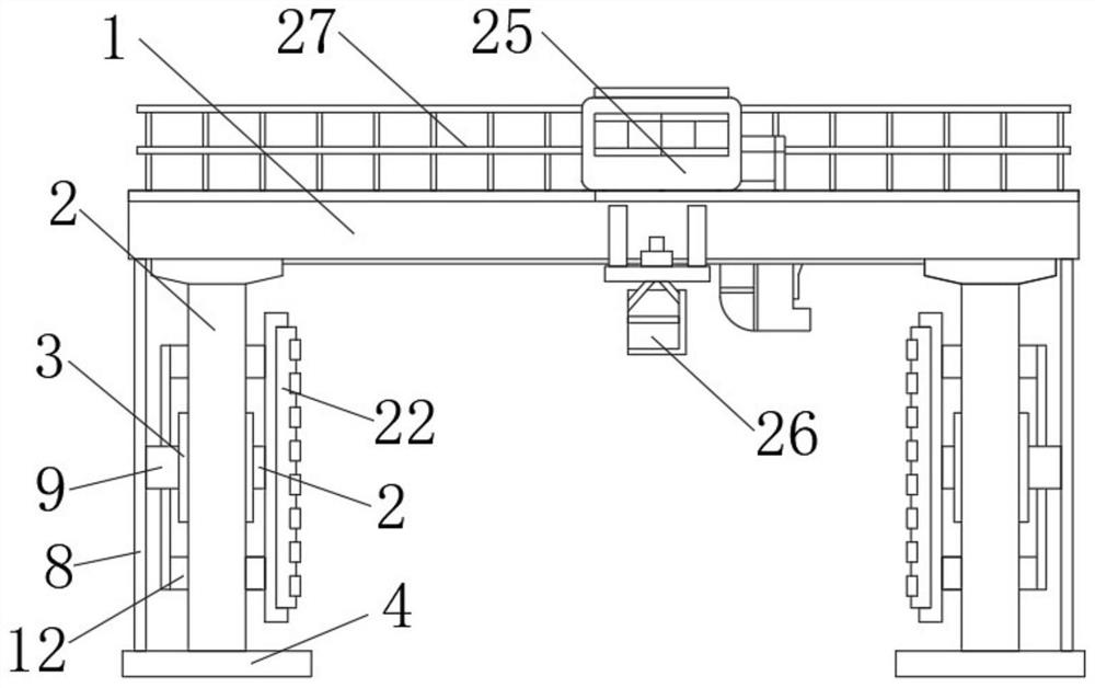
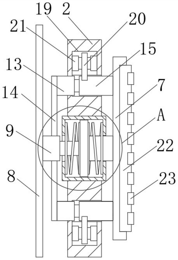
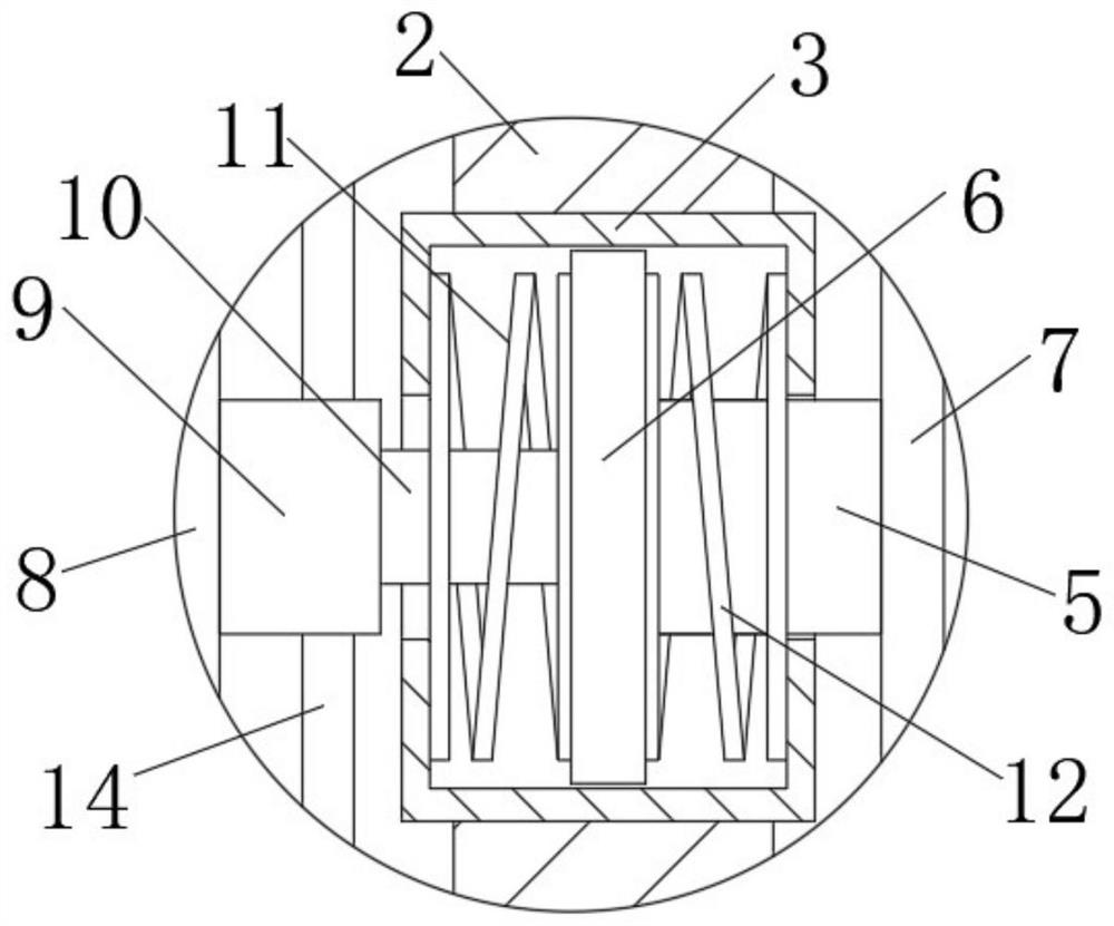
[0028] see Figure 1-5, an anti-collision support structure for dock lifting equipment, including a main beam frame 1, support columns 2 are fixedly installed on both sides of the bottom end of the main beam frame 1, and a mounting plate 4 is fixedly connected to the bottom end of the support column 2 , the middle part of the support column 2 is fixedly connected with the first connecting cylinder 3, one end of the first connecting cylinder 3 is slidably connected with the mounting column 5, the inner wall of the first connecting cylinder 3 is slidably connected with the sliding plate 6, and one end of the mounting column 5 is fixedly connected with the The middle part of one end of the sliding plate 6, one end of the sliding plate 6 is fixedly connected with the second spring 12, and the second spring 12 is positioned at the side wall of the mounting column 5, the other end of the mounting column 5 is fixedly connected with the mounting bracket 7, and the supporting column 2 ...

Embodiment 2

[0031] see Figure 1-5 , on the basis of Embodiment 1, a further improvement has been made: a fixed plate 8 is fixedly connected between the main beam frame 1 and the mounting plate 4, and one end of the fixed plate 8 is fixedly connected with a mounting tube 9, and the mounting tube 9 is slidably connected with a second A sliding column 10, and the first sliding column 10 is supported in the middle part of one end of the sliding plate 6; one end of the sliding plate 6 is fixedly equipped with a first spring 11, and the first spring 11 is positioned at the side wall of the first sliding column 10; the supporting column One end of 2 is fixedly connected with a second connecting cylinder 13, a second sliding column 16 is slidably connected between one end of the second connecting cylinder 13 and one end of the third connecting cylinder 15, and a first limit sliding column is slidably connected inside the second connecting cylinder 13. Disk 17, one end of the first limiting slidi...

Embodiment 3

[0034] see Figure 1-5 , made a further improvement on the basis of Embodiment 1: one end of the mounting frame 7 is fixedly installed with a protective pad 22, and one end of the protective pad 22 is fixedly connected with several vibration-damping rubber rings 23; between the two vibration-damping rubber rings 23 Several connection blocks 24 are fixedly connected, and the connection blocks 24 are located inside the protective pad 22 .

[0035] In this embodiment, a protective pad 22 is provided at one end of the mounting bracket 7, and then a plurality of vibration-damping rubber rings 23 are fixedly connected to one end of the protective pad 22, and several vibration-damping rubber rings 23 are connected together by a connecting block 24, So that the goods can be better supported.


PUM


Abstract

The invention relates to the technical field of lifting equipment, and discloses an anti-collision support structure for dock lifting equipment, which includes a main beam frame, and supporting columns are fixedly installed on both sides of the bottom end of the main beam frame. The bottom end of the support column is fixedly connected with a mounting plate, the middle part of the support column is fixedly connected with a first connecting cylinder, one end of the first connecting cylinder is slidably connected with a mounting column, and the inner wall of the first connecting cylinder is slidably connected with a sliding One end of the mounting column is fixedly connected to the middle of one end of the sliding plate, and a second spring is fixedly connected to one end of the sliding plate, and the second spring is located on the side wall of the mounting column. The anti-collision support structure used for dock lifting equipment can better protect the lifting equipment, avoid damage to the lifting equipment during the process of hoisting goods, and can better protect the anti-collision structure The buffer guide is fixed to reduce the shaking of the lifting equipment during the buffer process and avoid damage to the cargo due to impact.

Description

technical field [0001] The invention relates to the technical field of lifting equipment, in particular to an anti-collision support structure for dock lifting equipment. Background technique [0002] Hoisting machinery refers to electromechanical equipment used for vertical lifting or vertical lifting and horizontal moving of heavy objects. Its scope is defined as lifts with a rated lifting capacity greater than or equal to 0.5t; A crane equal to 2m and an electric hoist with a fixed load-bearing form, etc. [1] According to the "Special Equipment Catalog" promulgated by the AQSIQ, lifting machinery is divided into: bridge cranes, gantry cranes, tower cranes, mobile cranes, portal cranes, elevators, cable cranes, masts Cranes, mechanical parking equipment. [0003] Lifting machinery lifts or lifts and moves heavy objects through lifting hooks or other pick-up devices. The working process of hoisting machinery generally includes steps such as lifting, running, lowering and...

Claims


Application Information

Patent Timeline
Patent Type & Authority Patents(China)
IPC IPC(8): B66C5/02B66C15/04B66C19/00F16F15/08
CPCB66C19/00B66C5/02B66C15/04F16F15/085B66C2700/01
Inventor 钱进
Owner 东台永胜盈华游艇有限公司
Why Eureka
Try Eureka