[0035] The technical solutions in the embodiments of the present invention will be clearly and completely described below in conjunction with the accompanying drawings in the embodiments of the present invention. Obviously, the described embodiments are only a part of the embodiments of the present invention, rather than all the embodiments. Based on the embodiments of the present invention, all other embodiments obtained by those of ordinary skill in the art without creative work shall fall within the protection scope of the present invention.
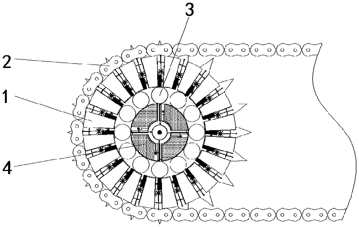
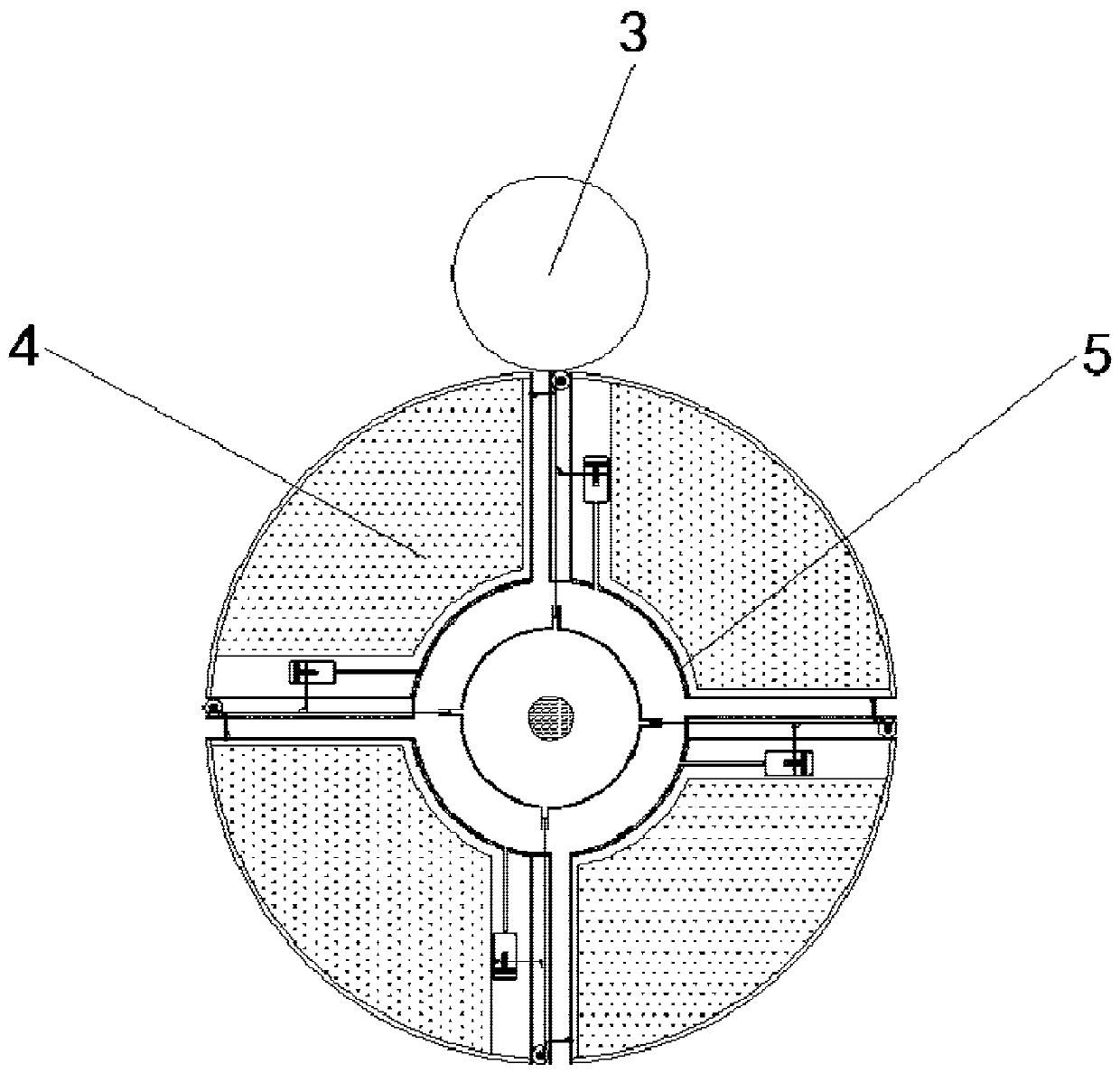
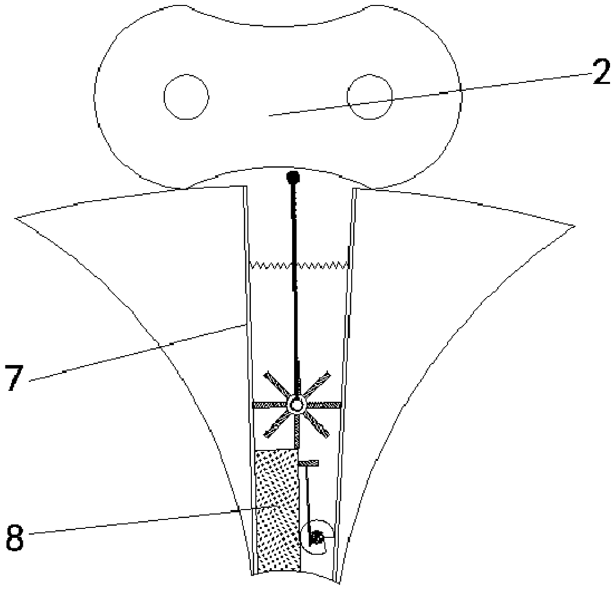
[0036] See Figure 1-9 , A decontamination grid machine that can automatically lubricate the rotating mechanism, including the rotating wheel 1, the material of the rotating wheel 1 is stainless steel, which can effectively prevent the equipment from being corroded, greatly extend the service life of the equipment, and reduce the production cost. It has an indispensable role for the enterprise. The surface of the rotating wheel 1 is meshed and connected with a transmission chain 2, and the inside of the rotating wheel 1 is provided with a bearing shaft 4, and the surface of the bearing shaft 4 is provided with a roller 3. The roller 3 is rotating normally. It is in contact with the receiving wheel 17, but the friction force generated is not enough to drive the receiving wheel 17 to rotate. The receiving shaft 4 is provided with an oil outlet tank 5, the surface of the oil outlet tank 5 is fixedly connected with an oil pipe 14, and the inside of the oil pipe 14 is fixedly connected with Separate partition 15, the side of the partition 15 is interspersed with a liquid barrier 18, the side of the liquid barrier 18 close to the partition 15 is provided with an extrusion rack 16 and the side of the extrusion rack 16 is provided with an arc The side surface of the squeeze rack 16 engages and connects with a receiving wheel 17. The receiving wheel 17 is provided with a spring. The side of the squeezing rack 16 away from the partition plate 15 is provided with a horizontal rack 21. 21 is engaged with the threaded rod 11 in one direction to prevent the threaded rod 11 from resetting, so that the lubricating oil cannot be squeezed into the communication pipe 20 next time. The side of the horizontal rack 21 is engaged and connected with the threaded rod 11, and the side of the horizontal rack 21 is slidingly connected There is an oil storage tank 19, the bottom of the oil storage tank 19 is fixedly connected with a communication pipe 20, and the opposite sides of the two receiving racks 16 are slidably connected to an air bag 6, and the air bag 6 is provided with a pressure sensor switch to control the suction wheel 10 according to the pressure. The inner wall of the rotating wheel 1 is provided with a liquid spray tube 7, and the inner wall of the liquid spray tube 7 is fixedly connected with a windshield 8. The side of the windshield 8 is slidably connected with an oil discharge vessel 12. The material of the oil discharge vessel 12 is stainless steel. It can effectively prevent the equipment from being corroded, greatly extend the service life of the equipment, reduce the production cost, and play an indispensable role for the enterprise. The surface of the tanker 12 is provided with grooves, and the grooves are inward when not rotating , The inner wheel surface of the oil discharge wheel 12 is meshed and connected with a windshield rod 13, the inside of the spray pipe 7 is provided with a suction wheel 10, and the inner wheel surface of the suction wheel 10 is provided with an annular protrusion, which continuously pushes the dredge rod 9 up, The drive chain 2 is dredged inside, and a dredging rod 9 is slidingly connected to the inner surface of the suction wheel 10.
[0037] After the grid machine runs for a long time, the sewage passes between the bearing shaft 4 and the rotating wheel 1 to contaminate the internal roller 3, and the friction coefficient on the surface of the roller 3 increases.
[0038] Since the roller 3 supports the rotating wheel 1 and the bearing shaft 4, when the rotating wheel 1 rotates, the roller 3 will rub against the contact surfaces of the two, so the roller 3 rotates, and the bearing wheel 17 provided inside the bearing shaft 4 In contact with the roller 3, due to the low surface friction coefficient of the roller 3 under the action of lubricating oil, the roller 3 cannot drive the receiving wheel 17 to rotate. However, when the sewage contaminates the lubricating oil, the lubrication effect is weakened, resulting in the surface of the roller 3 The friction coefficient increases, so during the rotation of the roller 3, the receiving wheel 17 will be driven by the friction between the two to rotate.
[0039] The rotation of the receiving wheel 17 drives the center of the squeezing rack 16, and the protrusions on the side push the liquid barrier 18, so that the liquid barrier 18 opens the oil pipe 14, and at the same time, the receiving rack squeezes the air inside the airbag 6, so that The air pressure inside the airbag 6 increases and expands, squeezing the lubricating oil in the oil outlet tank 5 into the oil pipe 14, and finally enters between the bearing shaft 4 and the rotating wheel 1 to re-lubricate the rollers 3.
[0040] Since a pressure sensor switch is provided in the airbag 6, when the air pressure in the airbag 6 increases, the opening of the pressure switch will start the motor that controls the suction wheel 10, so that the suction wheel 10 rotates, and the spray pipe is sprayed through the fan blades provided on the surface. 7 The internal gas is discharged, and the formed air flow drives the windshield 13 to engage and drive with the oil discharge wheel 12. The oil discharge wheel 12 rotates to open the spray pipe 7 and under the action of centrifugal force, the lubricating oil contaminated by sewage enters the spray pipe 7 and ejected from the inside of the transmission chain 2 under the action of the suction wheel 10, and the arc-shaped protrusions provided on the inner surface of the suction wheel 10 continuously push the dredge rod 9 toward the inside of the transmission chain 2, making the inside of the transmission chain 2 possible The debris and sludge brought in by the sewage are pushed out, and then washed by the lubricant, so as to achieve the effect of washing the transmission chain 2 through the discharged lubricant.
[0041] Since the contaminated lubricating oil flows out from the spray pipe 7 and the roller 3 is re-lubricated by the newly entered lubricating oil, the friction force between the roller 3 and the receiving wheel 17 is reduced, which makes the spring set inside the receiving wheel 17 Under the action of reverse rotation, the liquid barrier 18 moves under the action of the reset rod provided on its surface to block the oil pipe 14 again, and the airbag 6 loses the squeezing effect of the rack rod and restores the original air pressure. The internal pressure sensor switch is closed, and the motor that controls the suction wheel 10 loses power.
[0042] As the suction wheel 10 gradually stops rotating, the air flow inside the spray pipe 7 disappears, causing the windshield 13 to lose the pulling force of the oil outlet 12. Under the action of the spring set inside the oil outlet 12, it rotates in the opposite direction to turn the spray pipe 7 Blocked again.
[0043] Based on the above expression, the grid machine has completed the discharge of the contaminated lubricating oil when the sewage enters the bearing, and the re-lubrication of the roller 3 through the new lubricating oil, so as to achieve that when the sewage penetrates into the bearing, it will automatically be contaminated The lubricating oil is discharged, and the effect of re-lubricating the roller 3.
[0044] When the squeezing rack 16 moves, the horizontal rack 21 is squeezed and moved by the protrusion provided on the other side, and engages with the threaded rod 11, so that the threaded rod 11 moves inwardly, thereby driving the internal pushing of the oil storage tank 19. The liquid block squeezes the lubricating oil in the liquid storage tank into the communication pipe 20 and finally enters the oil outlet tank 5 to supplement the oil outlet tank 5 so as to achieve the effect of keeping the amount of lubricating oil in the oil outlet tank 5 constant.