Hydraulic oil tank with built-in leather bag and rotatable position

A technology of rotating position and hydraulic oil tank, applied in the direction of oil supply tank device, mechanical equipment, etc., can solve the problems of hydraulic oil pollution, increased gas content, not conducive to the precise control of the hydraulic system, etc. achieve the effect of isolation

Pending Publication Date: 2020-07-10
XINXIANG XINBEIZENG AUTOMATIC EQUIP CO LTD
View PDF0 Cites 0 Cited by
  • Summary
  • Abstract
  • Description
  • Claims
  • Application Information

AI Technical Summary

Problems solved by technology

[0005] Disadvantages: a. Since the air outside the fuel tank is often mixed and exchanged with the air inside the fuel tank, it will cause pollution (moisture, dust) to the hydraulic oil in the fuel tank. It is suitable for occasions where the working environment is relat

Method used


Image

  • Hydraulic oil tank with built-in leather bag and rotatable position
  • Hydraulic oil tank with built-in leather bag and rotatable position
  • Hydraulic oil tank with built-in leather bag and rotatable position

Examples


Embodiment Construction

[0022] The present invention will be described in detail below in conjunction with the accompanying drawings. It should be noted that the orientation terms such as left, middle, right, up, and down in the examples of the present invention are only relative concepts or refer to the normal use state of the product, and should not be considered as restrictive .

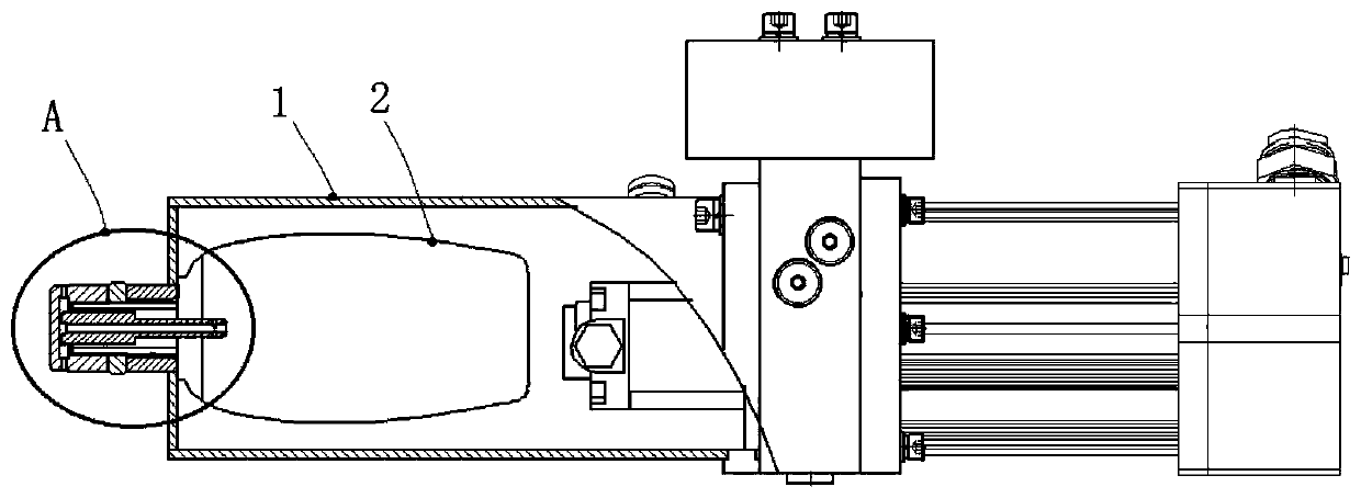
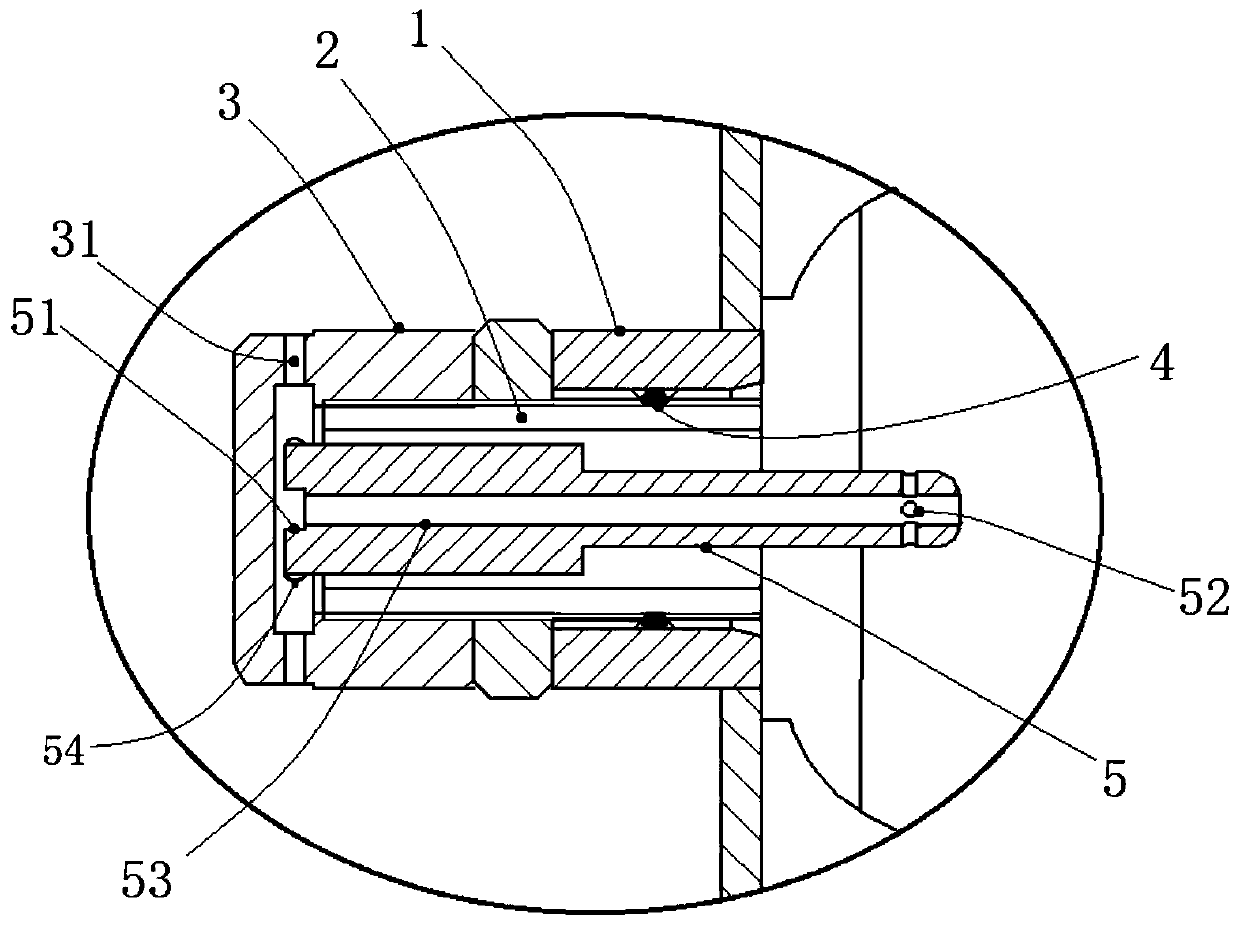
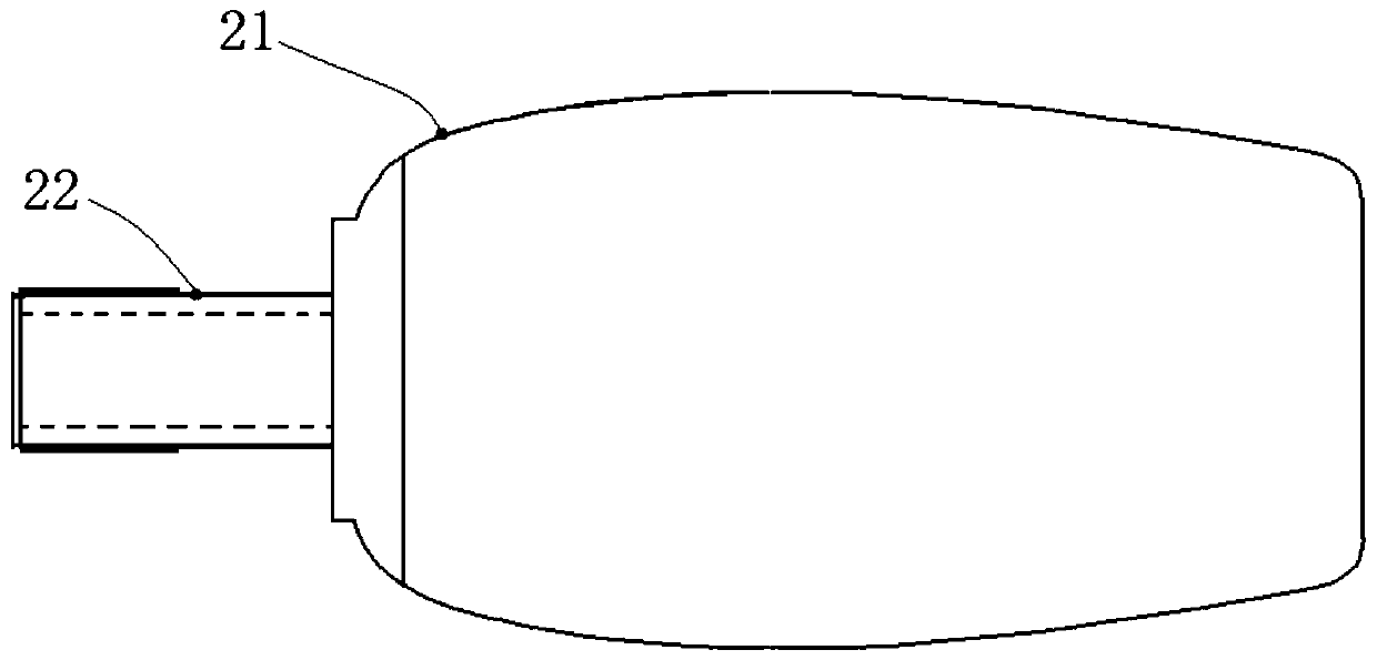
[0023] A hydraulic tank with a built-in bladder and a swivel position, such as figure 1 with figure 2 As shown, including the fuel tank 1, the working pressure of the fuel tank 1 is within 0~2Mpa, the working pressure of the hydraulic system is less than 21Mpa, and an air bag 2 is fixed in the fuel tank 1, and a first vent hole is opened on the air bag 2, A second vent hole is opened on the fuel tank 1, the first vent hole communicates with the second vent hole, and a vent rod 5 is fixed in the second vent hole, and the inner end of the vent rod 5 Located in the air bag 2, air holes 52 are distributed on the inner e...


PUM


Abstract

The invention provides a hydraulic oil tank with a built-in leather bag and a rotatable position. The hydraulic oil tank comprises an oil tank body. An air bag is fixedly arranged inside the oil tankbody. The air bag is provided with a first vent hole. A second vent hole is formed in the oil tank body. The first vent hole communicates with the second vent hole. A ventilation rod is fixedly arranged inside the second vent hole. The inner end of the ventilation rod is located inside the air bag. Air passing holes are distributed in the inner end of the ventilation rod. All the air passing holescommunicate with an air channel arranged inside the ventilation rod, and the second vent hole and the air channel both communicate with external air. By arranging the ventilation rod at the vent holein the air bag, on one hand, the phenomenon that the vent holes in the oil tank body are blocked by the contractive air bag can be effectively avoided; on the other hand, the air passing holes are distributed in the ventilation rod, exhaust pressure at the vent holes in the oil tank body can be relieved in an effective way, and the phenomenon that the air bag is damaged due to the fact that the vent holes are plugged and the air bag is stretched can be avoided.

Description

technical field [0001] The invention relates to a hydraulic oil tank, in particular to a hydraulic oil tank with a built-in leather bag and a rotatable position. Background technique [0002] At present, the known hydraulic oil tanks usually adopt the following two methods (open oil tank and closed oil tank): [0003] 1. Open fuel tank (such as Figure 4 ) [0004] This hydraulic oil tank has a simple structure and is suitable for most occasions. Features: The oil level in the oil tank is connected to the atmosphere through the air filter on the oil tank, so as to meet the change in volume when the equipment needs oil during operation (air can supplement the change in the amount of oil in the oil tank). [0005] Disadvantages: a. Since the air outside the tank is often mixed and exchanged with the air inside the tank, it will cause pollution (moisture, dust) to the hydraulic oil in the tank, and is suitable for occasions where the working environment is relatively good. b...

Claims


Application Information

Patent Timeline
IPC IPC(8): F15B1/26
CPCF15B1/26
Inventor 胡东涛张建明李彦俊刘峰岭
Owner XINXIANG XINBEIZENG AUTOMATIC EQUIP CO LTD
Why Eureka
Try Eureka