Control system and method for automatically pushing steel into furnace of steel pushing type stepping heating furnace

A control method and control system technology, which is applied in the field of automatic steel pushing into the furnace control system, can solve the problems of cold air inhalation, feeding furnace door can not fall, thermal efficiency loss, etc.

Active Publication Date: 2020-07-10
新余钢铁股份有限公司
View PDF4 Cites 7 Cited by
  • Summary
  • Abstract
  • Description
  • Claims
  • Application Information

AI Technical Summary

Problems solved by technology

[0002] The steel loading design of the walking heating furnace is generally two types: end steel feeding into the furnace and pushing steel into the furnace. A section of transition bench synchronized with the stepping mechanism is designed at the furnace feeding end of the push steel walking furnace. The transition bench is located between the roller table and the furnace. Between the walls, that is, outside the furnace, the fixed beams and movable beams in the furnace are extended by the stepping mechanism installed on the transition platform, but it is not a water beam design, but a set of steel structure frames; when working, the billet is pushed by th

Method used


Image

  • Control system and method for automatically pushing steel into furnace of steel pushing type stepping heating furnace
  • Control system and method for automatically pushing steel into furnace of steel pushing type stepping heating furnace

Examples


Embodiment Construction

[0025] With reference to the accompanying drawings, the specific implementation of the present invention will be further described in detail through the description of the embodiments to help those skilled in the art have a more complete, accurate and in-depth understanding of the inventive concept and technical solution of the present invention.

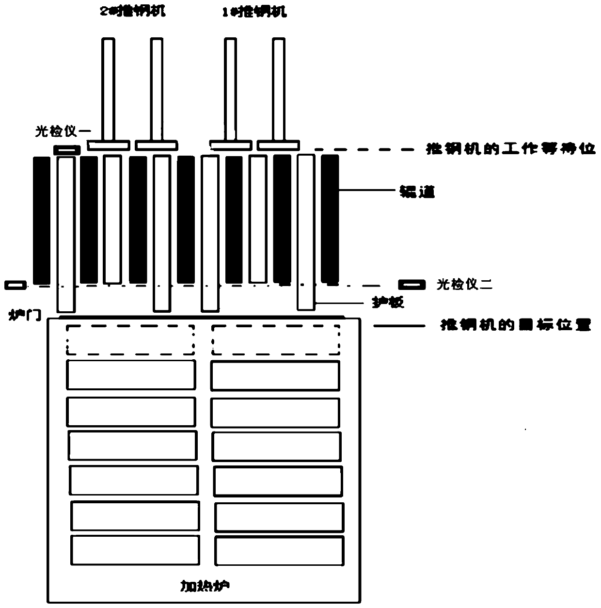
[0026] figure 1 This is a schematic diagram of the automatic steel pushing-in-furnace control structure of the push-steel step heating furnace provided by the embodiment of the present invention. For ease of description, only the parts related to the embodiment of the present invention are shown.

[0027] The system includes:

[0028] The pusher is located opposite the furnace door at the feeding end of the heating furnace, and is located on the side of the conveying roller drive motor. The pusher and the conveying roller are arranged horizontally. The pusher is at a standstill position or the coupling position of the conveying roller drive...


PUM


Abstract

The invention discloses a control system and method for automatically pushing steel into a furnace of the steel pushing type stepping heating furnace. The method comprises the following steps of waiting for steel pushing after a blank is centered at a blank waiting station; sending out a furnace door opening prompt if a stepping beam is in a lower position and an empty space in the furnace meets asteel pushing distance; opening a furnace door to a high position based on a furnace door opening command, and sending out a steel pushing prompt based on a position signal of the opened furnace door; pushing, by a steel pushing machine in a work waiting station based on a steel pushing command, the blank to advance to push the blank on a conveying roller way onto a fixing beam in the furnace; sending a reset command to the steel pushing machine after the steel pushing machine reaches the target position, and retracting the steel pushing machine to the work waiting station; and sending out afurnace door closing prompt after the steel pushing machine retracts to the work waiting station, performing, by the furnace door based on a furnace door closing command, closing action till the furnace door is completely closed. The furnace door is in an opened state only in the process of pushing the steel into the furnace, and the furnace door is in a closed state in the other time, so that theheat efficiency loss is greatly reduced.

Description

Technical field [0001] The present invention belongs to the technical field of walking heating furnaces. More specifically, the present invention relates to a control system and method for automatically pushing steel into the furnace of a pushing steel walking heating furnace. Background technique [0002] The steel loading design of the walking heating furnace is generally two types: the end steel entering the furnace and the pushing steel entering the furnace. The pushing steel entering the furnace is designed with a transition table synchronized with the walking mechanism. The transition table is located between the roller table and the furnace. Between the walls, that is, located outside the furnace, the fixed beams and movable beams in the furnace of the walking mechanism installed on the transition table extend, but are not designed for water beams, but are just a set of steel structure frames; when working, the blanks are pushed by the steel pusher The upper transition pla...

Claims


Application Information

Patent Timeline
IPC IPC(8): F27B9/40F27B9/24
CPCF27B9/2407F27B9/40
Inventor 刘永龙周萍肖颖谢爱平周焱民唐法丁李玉清束家彪赵房亮
Owner 新余钢铁股份有限公司
Why Eureka
Try Eureka