A laminar flow measurement device that can replace the measured pipe

A measuring device and measuring tube technology, which is applied in the direction of measuring devices, machine/structural component testing, fluid dynamics testing, etc., can solve the problems of poor persuasiveness and single measurement data, and achieve strong contrast, persuasiveness and stability The effect of the pressure value

Active Publication Date: 2021-12-03
西仪服(郑州)科技有限公司
View PDF0 Cites 0 Cited by
  • Summary
  • Abstract
  • Description
  • Claims
  • Application Information

AI Technical Summary

Problems solved by technology

[0005] In order to solve the problem in the background technology that the measured pipe fittings in the existing laminar flow experiments cannot be replaced, resulting in single measurement data and poor convincingness, the present invention proposes a laminar flow measurement device that can replace the measured pipe fittings

Method used


Image

  • A laminar flow measurement device that can replace the measured pipe
  • A laminar flow measurement device that can replace the measured pipe
  • A laminar flow measurement device that can replace the measured pipe

Examples


Embodiment 1

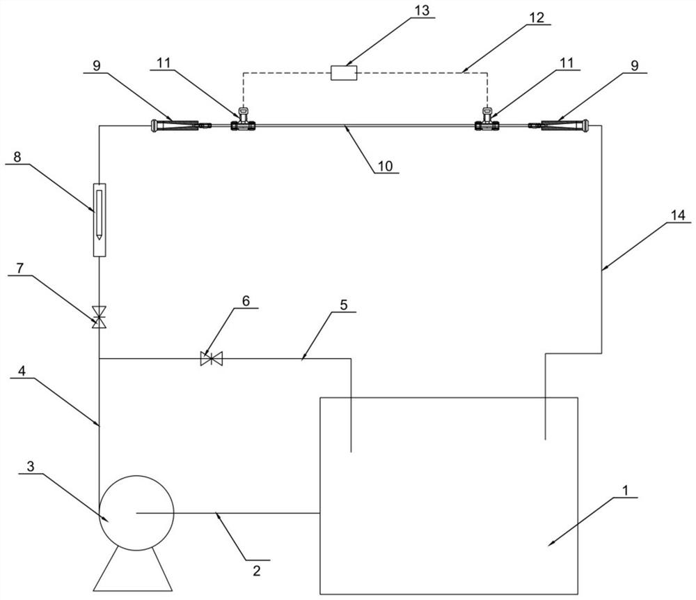
[0023] Embodiment 1: a kind of laminar flow measurement device that can replace the measured pipe, such as figure 1 As shown, it includes a circulating water tank 1, a main water delivery pipe 4 and a return pipe 14. The circulating water tank 1 is connected to the suction port of the centrifugal pump 3 through the water diversion pipe 2, and the water outlet of the centrifugal pump 3 is connected to the main water delivery pipe 4, and the water delivery The front part of the main pipe 4 is provided with a bypass regulating branch pipe 5 for pressure relief and steady flow, the bypass regulating branch pipe 5 is provided with a bypass regulating valve 6, and the middle part of the main water pipe 4 is provided with a flow regulating valve 7 and a flow meter 8. The flow regulating valve 7 and the flow meter 8 are located after the connection node between the bypass regulating branch pipe 5 and the main water pipe 4 . The bypass regulating branch pipe 5 is connected to the front...


PUM


Abstract

The invention provides a laminar flow measurement device which can replace the measured pipe, which solves the problem that the measured pipe cannot be replaced in the existing laminar flow experiment, resulting in single measurement data and poor convincingness. The invention includes a circulating water tank, a main water delivery pipe and a return pipe. The circulating water tank is connected to the suction port of the centrifugal pump through the water diversion pipe, and the water outlet of the centrifugal pump is connected to the main water delivery pipe. The main water delivery pipe is provided with a flow regulating valve 7 and flowmeter 8, the rear end of the main water pipe and the front end of the return pipe are provided with detachable laminar flow buffer joints, the pipe to be tested is connected between the two laminar flow buffer joints, and both ends of the pipe to be tested are equipped with There are pressure measuring holes in the annular gap, and the pipe fittings under test are equipped with pressure measuring joints covering the pressure measuring holes in the annular gap at both ends respectively. The measuring pipe fittings are connected in parallel to the pressure induction pipe, the pressure induction pipe is provided with a pressure difference sensor, and the back end of the return pipe is connected with the circulating water tank.

Description

technical field [0001] The invention relates to the field of fluid coefficient measurement, in particular to a laminar flow measurement device which can replace a measured pipe. Background technique [0002] Laminar flow is a state of flow of a fluid. When the fluid flows in the tube, its particle moves smoothly and linearly along the direction parallel to the tube axis. This kind of flow is called laminar flow or stagnant flow, also known as linear flow. The flow velocity of the fluid is greatest at the center of the tube and least near the wall. Laminar flow only occurs when the Reynolds number Re (Re=ρUL / μ) is small, that is, the fluid density ρ, the characteristic velocity U and the object characteristic length L are all small, or the fluid viscosity μ is large. When Re exceeds a certain critical Reynolds number Recr, laminar flow begins to transition to irregular turbulent flow due to disturbance, and the motion resistance increases sharply at the same time. For a c...

Claims


Application Information

Patent Timeline
Patent Type & Authority Patents(China)
IPC IPC(8): G01M10/00
CPCG01M10/00
Inventor 张克张新强杨会刘志伟
Owner 西仪服(郑州)科技有限公司
Why Eureka
Try Eureka