Radar tracking beam angle measurement method

A radar tracking and angle measurement technology, applied in the field of radar tracking beam angle measurement, can solve the problems of large S-curve data capacity and complex angle measurement process.

Active Publication Date: 2020-07-10
中国北方工业有限公司 +1
View PDF6 Cites 5 Cited by
  • Summary
  • Abstract
  • Description
  • Claims
  • Application Information

AI Technical Summary

Problems solved by technology

[0005] The technical problem to be solved in the present invention is how to provide a radar tracking beam angle measurement method to overcome the S-curve data of the existing single pulse and differe...

Method used


Image

  • Radar tracking beam angle measurement method
  • Radar tracking beam angle measurement method
  • Radar tracking beam angle measurement method

Examples


Embodiment Construction

[0032] In order to make the purpose, content and advantages of the present invention clearer, the specific implementation manners of the present invention will be further described in detail below in conjunction with the accompanying drawings and embodiments.

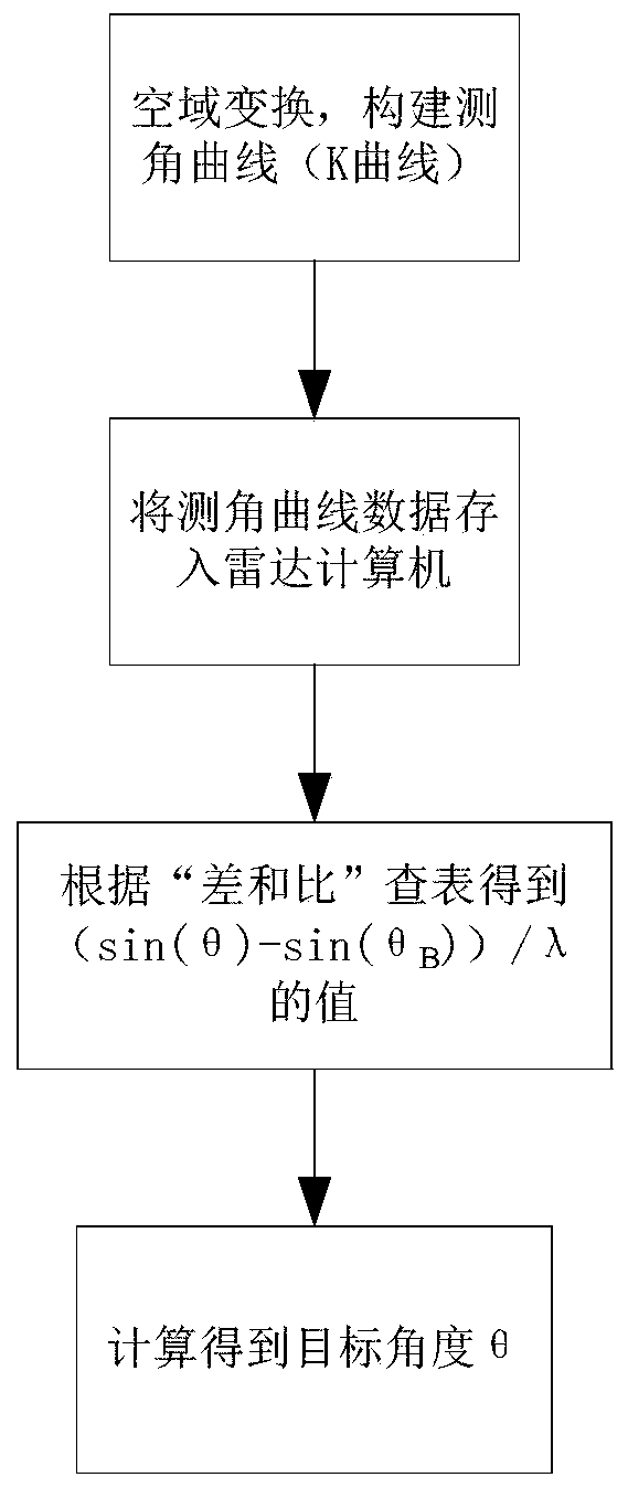
[0033] figure 1 It is the main flow chart of the technical solution of the present invention. Such as figure 1 Shown, the radar tracking beam angle measuring method that the present invention proposes comprises the following steps:

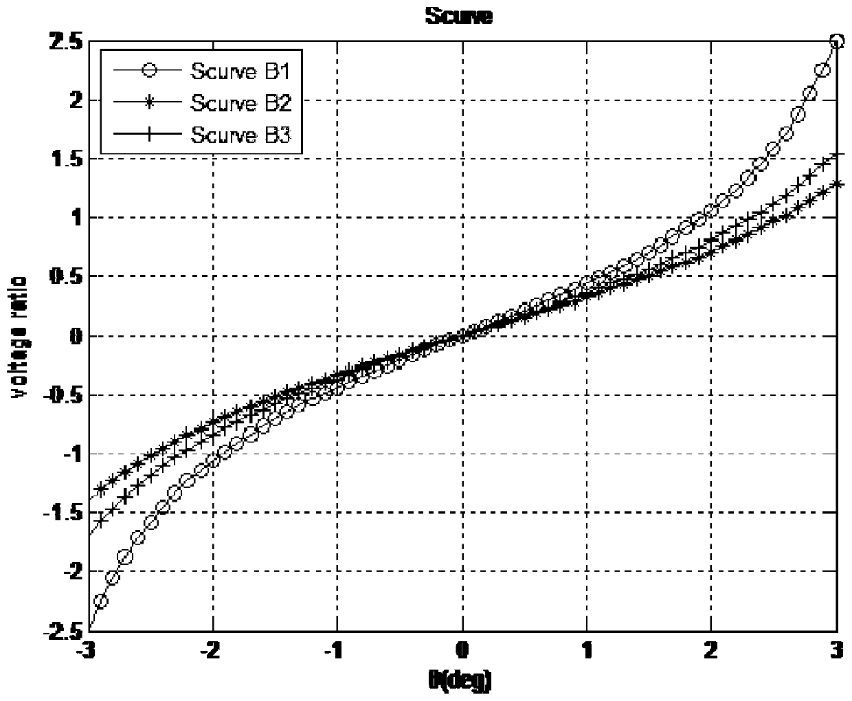
[0034] Step 1: Transform the space and construct the goniometric curve.

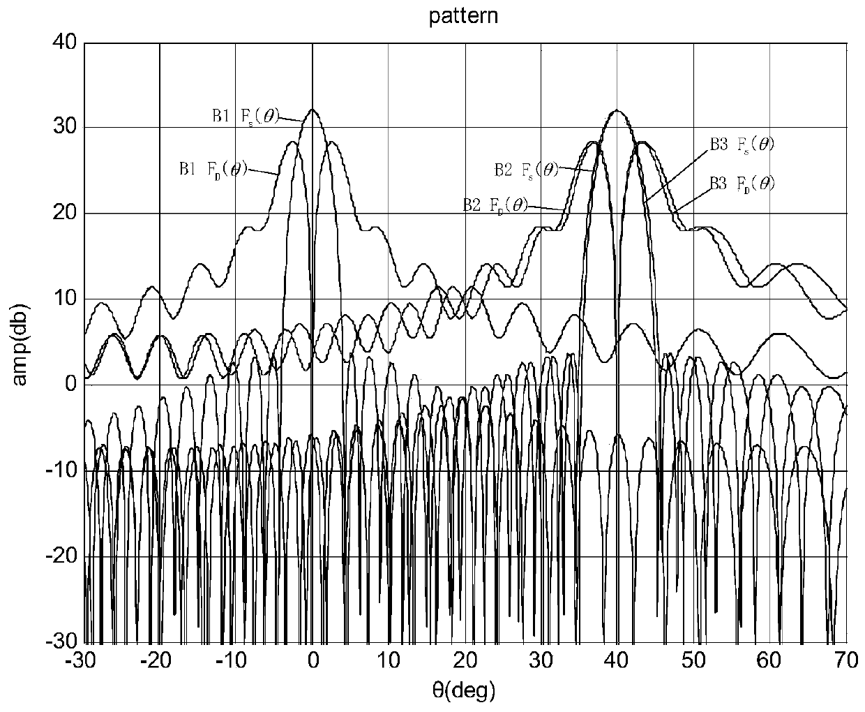
[0035] The sum beam pattern equation in theta domain is:

[0036]

[0037] The differential beam pattern equation in the θ domain is:

[0038]

[0039]

[0040] where a i is the amplitude weighting coefficient, θ is the angle of the target to be measured by the radar, θ B is the center pointing of the current tracking beam, d is the distance between antenna elements, N is the number of antenna elements,...


PUM


Abstract

The invention relates to a radar tracking beam angle measurement method, and belongs to the field of radar design. The objective of the invention is to overcome the problems of large S-curve data capacity and complex angle measurement process of an existing monopulse sum-difference beam amplitude comparison angle measurement method under the conditions of large airspace, any angle and multiple beams at the same time. The method comprises the steps of constructing a universal angle measurement curve (K curve) subjected to spatial domain transformation, the abscissa of the K curve is p, the ordinate of the K curve is the difference sum ratio (volt _ ratio), p = (sin (theta)-sin (theta B))/lambda, and storing K curve data into a radar computer; comparing the difference sum ratio (volt _ ratio) of the target echo actually measured by the radar with the K curve data, and looking up a table to obtain a corresponding p value; and calculating a target angle value according to theta = arcsin (p* lambda + sin (theta B)). The K curve obtained through spatial domain transformation is not affected by factors such as beam pointing and frequency, the data storage space is small, the table look-up process is simple, and single-pulse sum-difference amplitude comparison angle measurement under the conditions of large spatial domain, any angle and multiple beams at the same time can be simply and conveniently achieved.

Description

technical field [0001] The invention belongs to the field of radar design, in particular to a radar tracking beam angle measurement method. Background technique [0002] As an important sensor for battlefield perception in modern warfare, radar is the most basic and important function to track and detect the spatial position of the target, and the measurement of the target angle is an important part of it. With the development of phased array radar technology, the monopulse angle measurement method is widely used in radar angle measurement. This method includes ratio amplitude monopulse angle measurement and phase ratio monopulse angle measurement. most common. [0003] The monopulse and difference beam ratio amplitude angle measurement method forms a sum beam, an azimuth angle difference beam and an elevation angle difference beam at each wave position, and the horizontal axis can be obtained by the amplitude ratio of the difference beam pattern and the sum beam pattern as...

Claims


Application Information

Patent Timeline
IPC IPC(8): G01S7/292G01S13/44
CPCG01S7/292G01S13/44
Inventor 邱天张俊安薛广然朱永杰臧会凯崔向阳蒋明李选寅
Owner 中国北方工业有限公司
Why Eureka
Try Eureka