Optical cable connecting shell assembly and optical cable connector
A technology for optical cable connectors and housing components, which is applied in the field of optical cable connection housing components and optical cable connectors, can solve the problems of crimping failure, easy damage and breakage of support cylinder sections, etc. The effect of the crimping action
- Summary
- Abstract
- Description
- Claims
- Application Information
AI Technical Summary
Problems solved by technology
Method used
Image
Examples
specific Embodiment 1
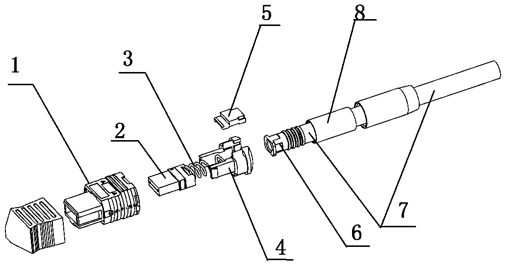
[0057] Optical cable connector of the present invention, such as figure 2 , image 3 and Figure 7 As shown, it includes an optical cable 7 and an optical cable connection housing assembly connected to one end of the optical cable 7. The optical cable connection housing assembly includes a front housing 1, a ferrule 2, a spring 3, a spring support seat 4, a cover plate 5, a support cylinder 6 and a pressing Socket 8, wherein the front shell 1 includes an inner shell and an outer shell.
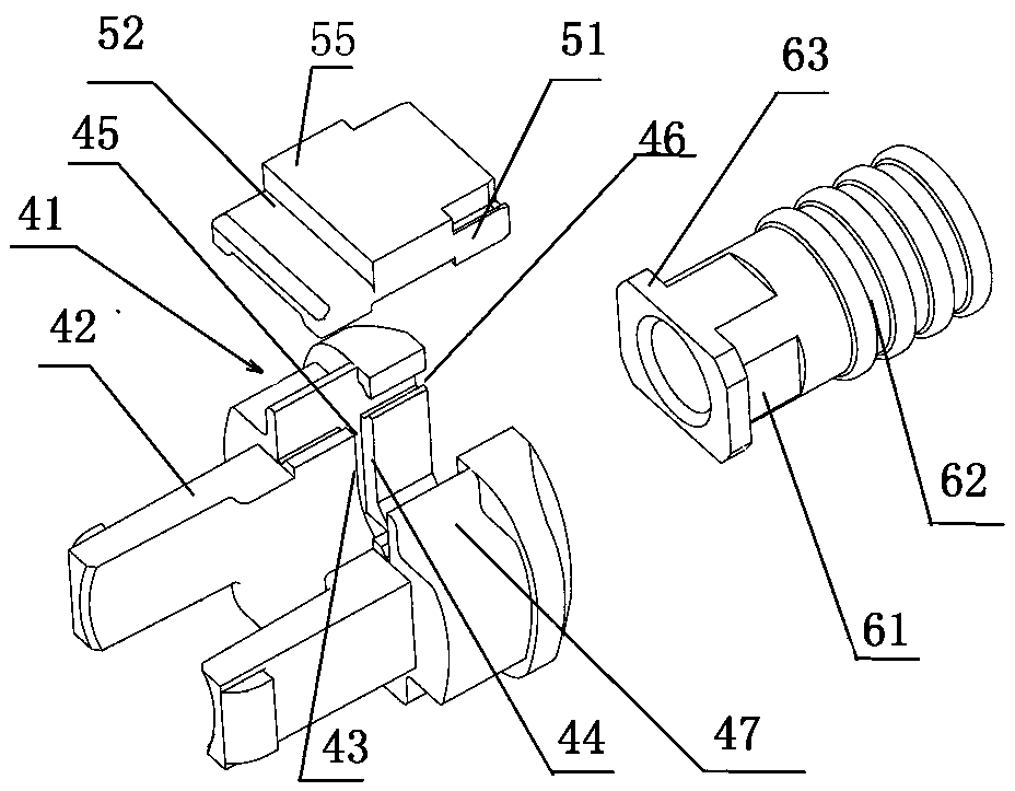
[0058] The spring support seat 4 has accommodating and supporting functions to the spring 3. The spring support seat 4 includes a U-shaped seat 41 and a connection structure 42. The connection structure 42 is an elastic clamping arm that is arranged on the front end of the U-shaped seat 41 and overhangs forward. The elastic clamping arm can be connected with the inner housing to form an anti-disengagement fit. The support cylinder 6 includes a connecting section 61 for connecting with the ...
specific Embodiment 2
[0067] The difference from Embodiment 1 is that the cover structure is hinged on one of the two side walls of the U-shaped seat, and the other side wall is provided with an elastic buckle, and the cover structure is provided with an opening that matches the elastic buckle. Holes, when the cover plate structure is installed, the cover plate structure can be rotated around the hinge shaft to the position of blocking the opening of the U-shaped seat, and after the elastic convex buckle is buckled with the opening, the cover plate installation is completed. After the spring support seat is connected with the inner casing, the rear end surface of the inner casing is at the front side of the cover structure, and when the outer casing slides backward relative to the inner casing to unlock, part of the cover structure is covered inside.
specific Embodiment 3
[0069] The difference from Example 1 is that the two side walls of the U-shaped seat are provided with elastic buckles, and the two ends of the cover structure corresponding to the positions of the elastic buckles are provided with openings matching the elastic buckles, and the cover structure is installed , the cover plate structure is placed to the position to block the opening of the U-shaped seat, and the cover plate structure is pressed down to fasten the elastic convex buckle with the opening, and the cover plate installation is completed. After the spring support seat is connected with the inner casing, the rear end surface of the inner casing is at the front side of the cover structure, and when the outer casing slides backward relative to the inner casing to unlock, part of the cover structure is covered inside.
PUM
 Abstract
Description
Claims
Application Information
 - R&D
- Intellectual Property
- Life Sciences
- Materials
- Tech Scout
- Unparalleled Data Quality
- Higher Quality Content
- 60% Fewer Hallucinations
Browse by: Latest US Patents, China's latest patents, Technical Efficacy Thesaurus, Application Domain, Technology Topic, Popular Technical Reports.
© 2025 PatSnap. All rights reserved.Legal|Privacy policy|Modern Slavery Act Transparency Statement|Sitemap|About US| Contact US: help@patsnap.com


