Holding tool device for automatically stacking fuel cell stacks

A fuel cell stack and automatic stacking technology, which is applied in the direction of fuel cells, circuits, electrical components, etc., can solve the problem that the small diameter of the positioning mechanism is difficult to ensure the accuracy of straightness, etc., the automatic stacking of stack materials has not been realized, and the automatic production and assembly cannot be applied and other problems, to achieve the effect of simple structure, stable transmission and good stability

Active Publication Date: 2020-07-10
DONGFENG MOTOR CORP HUBEI
View PDF22 Cites 1 Cited by
  • Summary
  • Abstract
  • Description
  • Claims
  • Application Information

AI Technical Summary

Problems solved by technology

The method and device do not realize the automatic stacking of stack materials, and the use of positioning holes in the materials requires taking out the positioning mechanism after the materials are stacked. The positioning mechanism is generally small in diameter and it is difficult to ensure the accuracy of straightness. At the same time, it is difficult to realize the automatic stacking of materials in the internal positioning method.
[0005] Chinese patent CN105304925A is named as a fuel cell stack assembly device. The fuel cell stack is positioned by the outer contour of the material, and is composed of a limiting part, a fixed frame and a bottom plate to ensure the stacking accuracy, but the limiting device of the device needs to be manually Installation and adjustment, not suitable for automated production assembly

Method used


Image

  • Holding tool device for automatically stacking fuel cell stacks
  • Holding tool device for automatically stacking fuel cell stacks
  • Holding tool device for automatically stacking fuel cell stacks

Examples


Embodiment Construction

[0032] The present invention will be further described in detail below in conjunction with the accompanying drawings and specific embodiments.

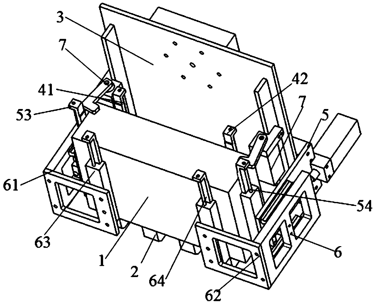
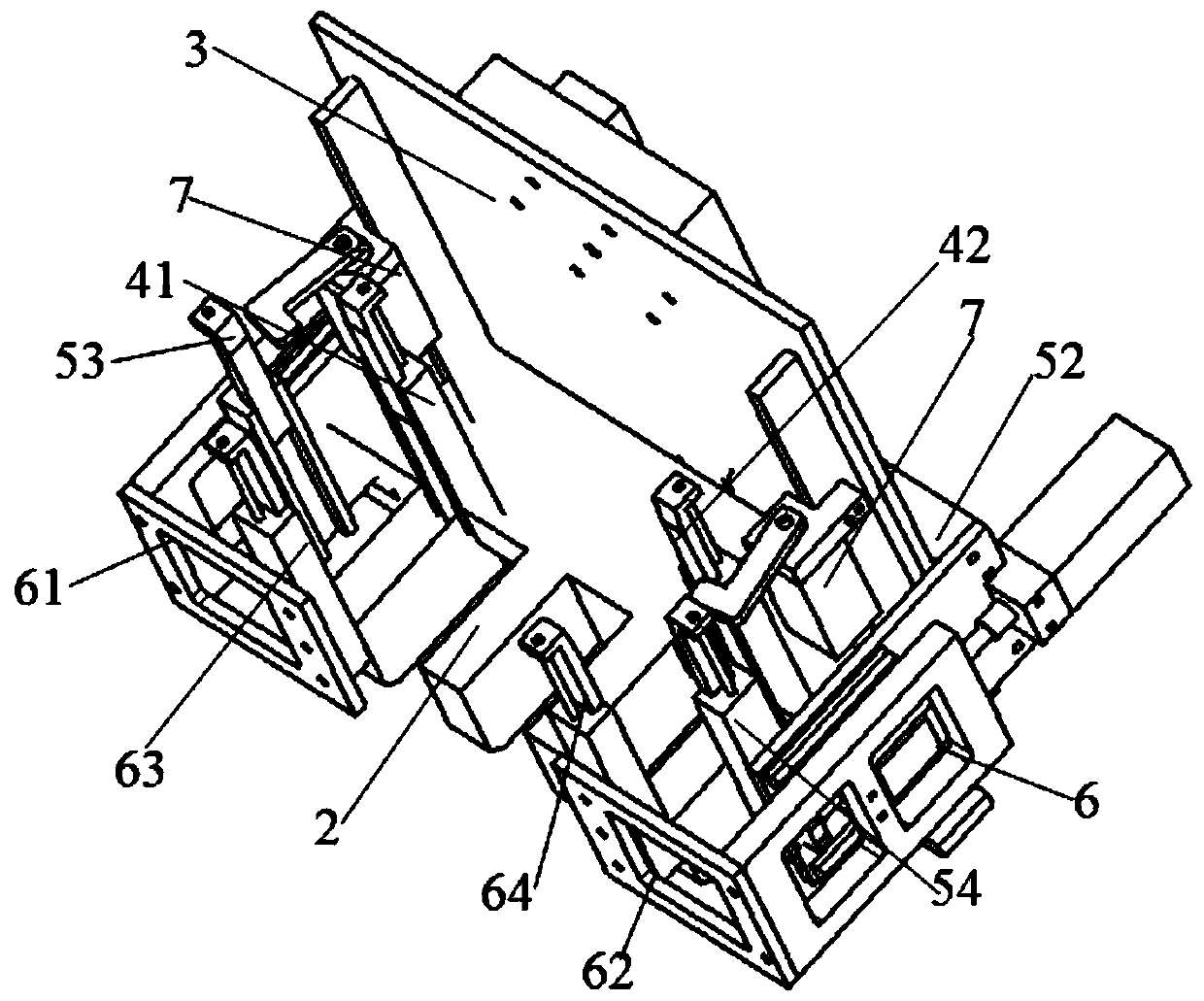
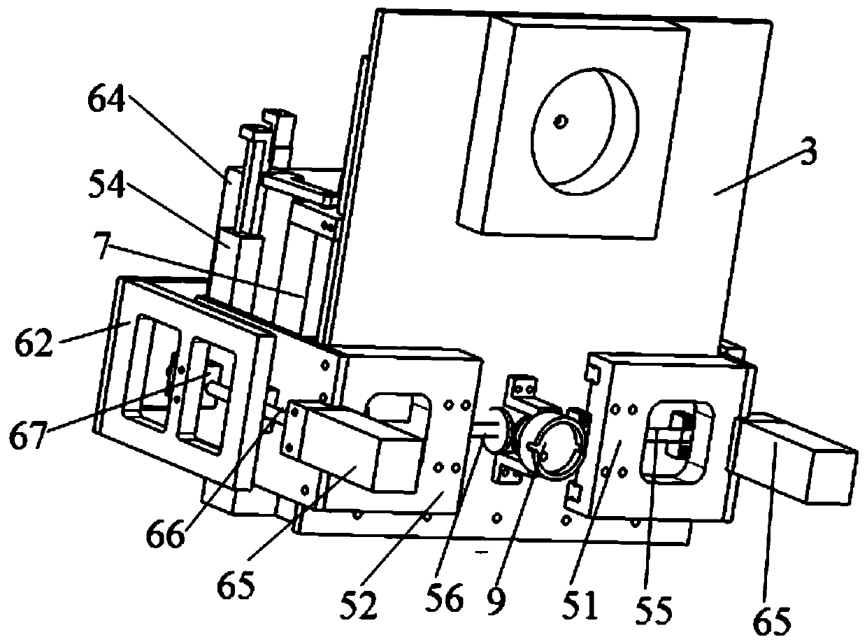
[0033] like Figure 1-7 As shown, the present invention provides a holding device for automatic stacking of fuel cell stacks, including a base plate 2 for placing the stack 1 and a back plate 3 fixedly connected to the base plate 2. A plurality of fixed base columns 4 arranged at intervals in the horizontal direction, the back plate 2 is provided with a first guide mechanism 5 that can be opened and closed horizontally, and cooperates with the lateral sides of the stack 1 to limit the position, the first guide mechanism 5 is in front of the fixed base column 4 There is a second guide mechanism 6 that can move longitudinally. The second guide mechanism 6 and the fixed base column 4 cooperate with the longitudinal sides of the electric stack 1 to limit the positions. Tight mechanism7. In this embodiment, the transverse direction is th...


PUM


Abstract

The invention discloses a holding tool device for automatically stacking fuel cell stacks. The device is characterized in that the device comprises a bottom plate which is used for placing an electricpile and a back plate which is fixedly connected to the bottom plate; the bottom plate is provided with a plurality of fixed base columns which are transversely arranged at intervals in front of theback plate; the back plate is provided with a first guide mechanism which can be transversely opened and closed and is matched with the two transverse sides of the galvanic pile for limiting; the first guide mechanism is provided with a second guide mechanism capable of longitudinally moving in front of the fixed base column, the second guide mechanism, the fixed base column and the two longitudinal sides of the electric pile are matched for limiting, and the bottom plate is further provided with a pressing mechanism capable of vertically pressing the electric pile. The transverse size of theelectric pile is controlled and kept through automatic opening and closing of the first guide mechanism, then the longitudinal size between the electric pile and the fixed base column is controlled through movement of the second guide mechanism, the electric pile is vertically pre-pressed and limited through the pressing mechanism after stacking is completed, and the electric pile can be stably transferred to a pressing station.

Description

technical field [0001] The invention relates to stacking of fuel cell stacks, in particular to a holding device for automatic stacking of fuel cell stacks. Background technique [0002] At present, most fuel cell stacks are stacked manually. The specific operation method is to manually install the material guide and limit device in place before stacking. The specified order of stacking is stacked one by one. Considering the large number of stacked materials such as membrane electrodes and bipolar plates, and the high requirements for their mutual positions, the gap adjustment of the guide limit device is particularly important, and the process of manually adjusting the guide device is cumbersome, time-consuming, and manually adjusted. Higher disadvantages are required. [0003] Chinese patent CN104835978A, titled Proton Exchange Membrane Fuel Cell Stack Automatic Assembly System, proposes a fuel cell stack automatic assembly process system from material assembly, compressi...

Claims


Application Information

Patent Timeline
IPC IPC(8): H01M8/2404
CPCH01M8/2404Y02E60/50
Inventor 夏沙史建鹏胡立中李洪涛贺挺
Owner DONGFENG MOTOR CORP HUBEI
Why Eureka
Try Eureka