A protective device for a high-voltage power distribution cabinet and its installation method

A technology for high-voltage power distribution cabinets and protective devices, which is applied to substation/distribution device housing, substation/switchgear cooling/ventilation, and substation/switch layout details, etc. Disassembly, difficult to store and other problems, to reduce wind, sun and rain, ensure safety, and improve safety

Active Publication Date: 2021-12-17
中电正控(北京)电气有限公司
View PDF5 Cites 0 Cited by
  • Summary
  • Abstract
  • Description
  • Claims
  • Application Information

AI Technical Summary

Problems solved by technology

[0002] High-voltage distribution cabinets refer to electrical products that are used for on-off, control or protection in power system power generation, transmission, distribution, power conversion and consumption. Due to the high voltage, there are certain risks. For safety reasons, it is usually Protective devices will be installed around it to prevent people from approaching, but the existing protective devices for high-voltage power distribution cabinets have certain defects: 1. The exposed parts of the device are easily oxidized and rusted, making it difficult to disassemble the device. Safety risk, 2. Only protect the surroundings of the power distribution cabinet. The top of the power distribution cabinet is not protected, and it is easy to get wet from rain and snow. At the same time, there is a risk of damage by human throwing. 3. It is not easy to store after disassembly and takes up a lot of space

Method used


Image

  • A protective device for a high-voltage power distribution cabinet and its installation method
  • A protective device for a high-voltage power distribution cabinet and its installation method
  • A protective device for a high-voltage power distribution cabinet and its installation method

Examples


Embodiment Construction

[0033] The following will clearly and completely describe the technical solutions in the embodiments of the present invention with reference to the accompanying drawings in the embodiments of the present invention. Obviously, the described embodiments are only some, not all, embodiments of the present invention. Based on the embodiments of the present invention, all other embodiments obtained by persons of ordinary skill in the art without making creative efforts belong to the protection scope of the present invention.

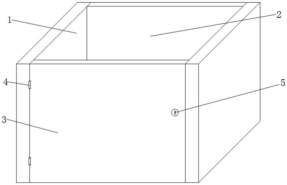
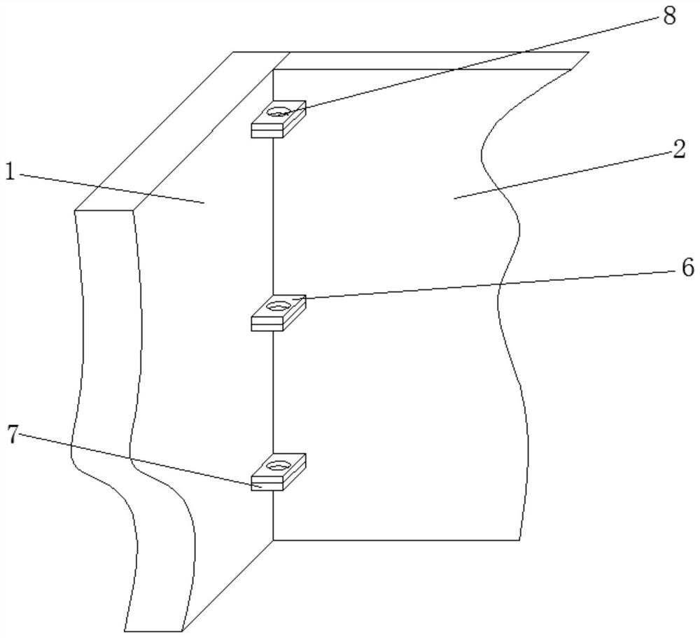
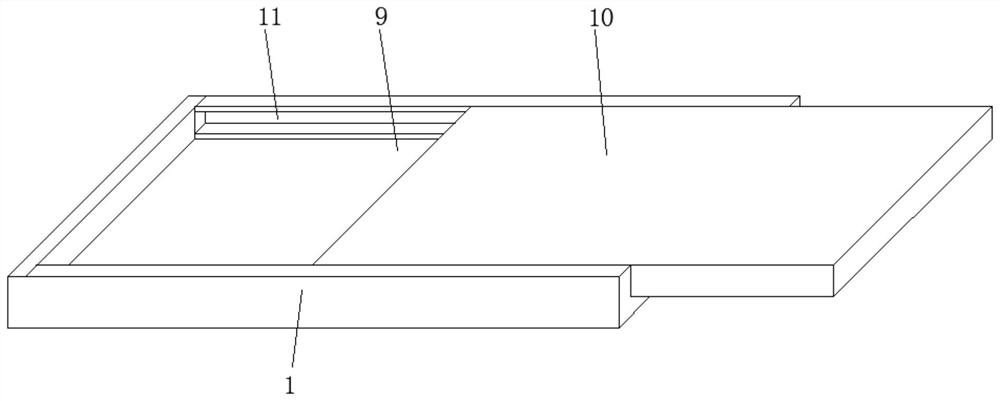
[0034] see Figure 1 to Figure 7 , the present invention provides a technical solution:

[0035] A protective device for a high-voltage distribution cabinet, such as figure 1 As shown, the first enclosure 1 is included, the rear end position between two adjacent first enclosures 1 is movably installed with a second enclosure 2, and the rear end between adjacent two first enclosures 1 is A door panel 3 is movably installed at the front end, and a hinge 4 is m...


PUM


Abstract

The invention discloses a protective device for a high-voltage power distribution cabinet, which includes a first enclosure, a second enclosure is movably installed at the rear end between two adjacent first enclosures, and two adjacent first enclosures are A door panel is movably installed at the front end between the first coaming panels, and a hinge is movably installed between one side of the door panel and the first coaming panel, and a door lock is provided at the middle position on the other side of the front end outer surface of the door panel. The first connecting seat is fixedly installed at the rear end position of the outer surface of the first enclosure close to the second enclosure, and the second connecting seat is fixedly installed on both sides of the front end outer surface of the second enclosure, and the second connection Both the seat and the first connecting seat are provided with perforations in the middle of the outer surface of the upper end, and the outer surface of the first enclosure away from the second enclosure is provided with a first sliding groove. The invention can protect the connection, avoid the damage of the connection and make it difficult to disassemble, can protect the power distribution cabinet in all directions, improves the safety of the power distribution cabinet, and is convenient for storage after the device is disassembled.

Description

technical field [0001] The invention relates to the technical field of power distribution cabinets, in particular to a protective device for a high-voltage power distribution cabinet and an installation method thereof. Background technique [0002] High-voltage distribution cabinets refer to electrical products that are used for on-off, control or protection in power system power generation, transmission, distribution, power conversion and consumption. Due to the high voltage, there are certain risks. For safety reasons, it is usually Protective devices will be installed around it to prevent people from approaching, but the existing protective devices for high-voltage power distribution cabinets have certain defects: 1. The exposed parts of the device are easily oxidized and rusted, making it difficult to disassemble the device. Safety risk, 2. Only the surrounding of the power distribution cabinet is protected. The top of the power distribution cabinet is not protected, and...

Claims


Application Information

Patent Timeline
Patent Type & Authority Patents(China)
IPC IPC(8): H02B1/30H02B1/28H02B1/56
CPCH02B1/306H02B1/28H02B1/565
Inventor 李洪涛
Owner 中电正控(北京)电气有限公司
Why Eureka
Try Eureka