
Photoelectric sensor switch monitoring protection circuit and monitoring method

A photoelectric sensor and switch monitoring technology, applied in electronic switches, instruments, electrical components, etc., can solve problems affecting sensor repeatability, sensor error, production efficiency and economy

Inactive Publication Date: 2020-07-10
南京雷仕光电科技有限公司
View PDF0 Cites 1 Cited by
  • Summary
  • Abstract
  • Description
  • Claims
  • Application Information

AI Technical Summary

Problems solved by technology

[0003] The photoelectric switch has good hysteresis characteristics, so even if the detected object shakes in a small range, it will not affect the output state of the driver, so that it can be kept in a stable working area; it is driven by light radiation, when a certain strong light When the photoelectric sensor is irradiated on the photosensitive element, the switch is triggered and the signal is output; when the photoelectric sensor switch in the prior art is working, due to the difference in the workplace, there will be false touches, which will lead to confusion in the production process, thereby affecting production efficiency and Economical; and when the mechanical components driven by the photoelectric sensor switch are abnormally damaged, the repeatability of the sensor will be affected, resulting in errors in the sensor

Method used


Image

  • Photoelectric sensor switch monitoring protection circuit and monitoring method
  • Photoelectric sensor switch monitoring protection circuit and monitoring method
  • Photoelectric sensor switch monitoring protection circuit and monitoring method

Examples


Embodiment Construction

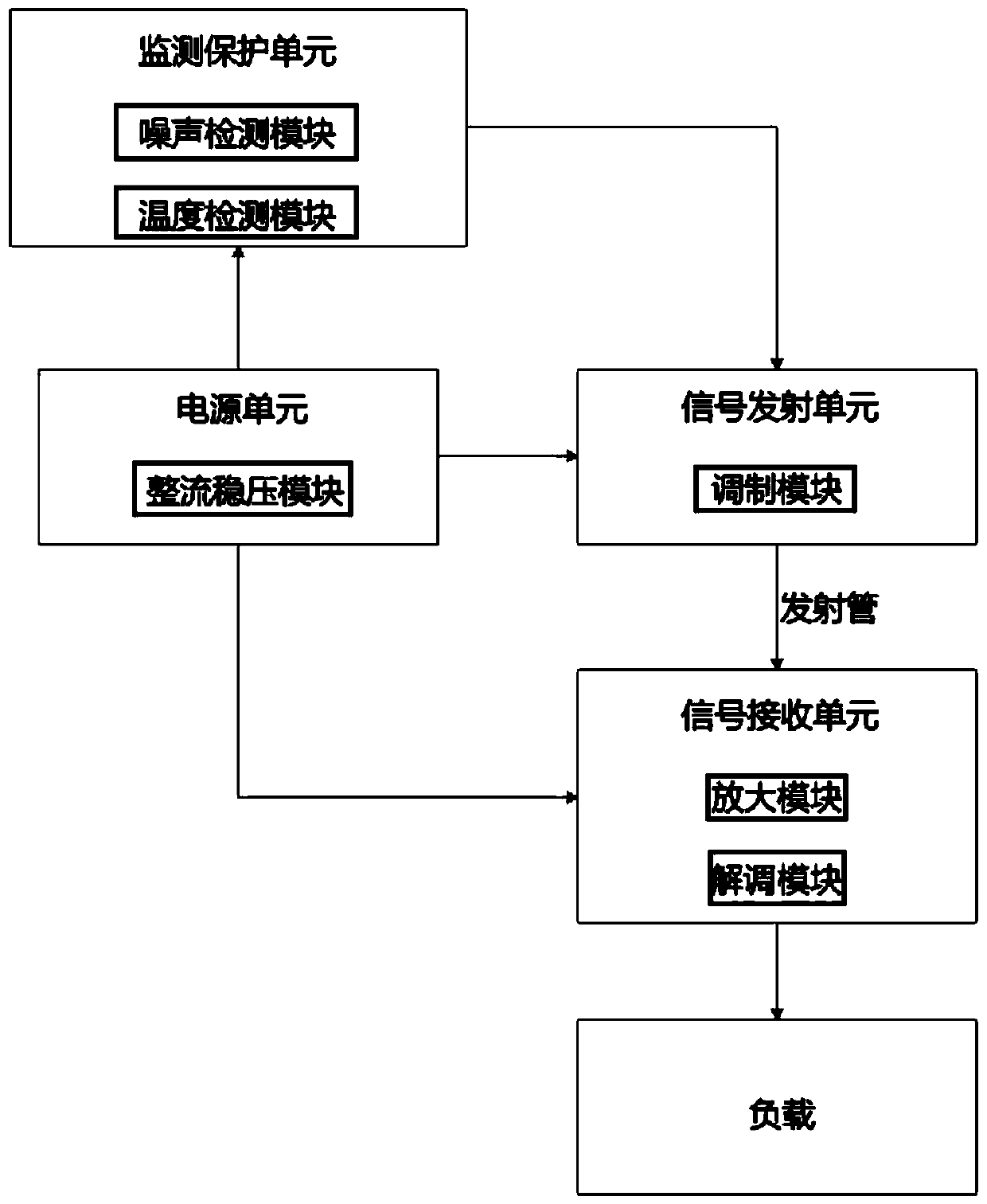
[0042] Such as figure 1 As shown, in this embodiment, a photoelectric sensor switch monitoring and protection circuit includes: a power supply unit, a signal transmitting unit, a signal receiving unit, and a monitoring and protection unit; wherein, the monitoring and protection unit also includes: a noise detection module and Temperature detection module;

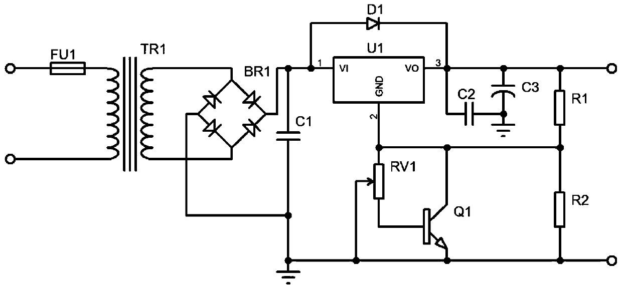
[0043] The power supply unit will input the voltage to the equipment, and convert the alternating current to direct current and stabilize the output voltage through the rectification and voltage stabilization module;

[0044] The signal transmitting unit controls the carrier waveform with the baseband pulse of the signal collected by the modulation module, so as to meet the emission standard of the signal transmitting tube;

[0045] The signal receiving unit converts the received optical pulse into an electric pulse signal by using the demodulation module, and simultaneously amplifies the received signal by using the ampli...


PUM


Abstract

The invention discloses a photoelectric sensor switch monitoring and protecting circuit and a monitoring method. The photoelectric sensor switch monitoring and protecting circuit comprises a power supply unit, a signal transmitting unit, a signal receiving unit and a monitoring and protecting unit, the photoelectric sensor switch monitoring and protecting circuit is characterized in that the monitoring protection unit further comprises a noise detection module and a temperature detection module; the power supply unit inputs voltage into equipment and converts alternating current into direct current and stable output voltage through the rectifying and voltage stabilizing module; the signal transmitting unit controls the carrier waveform of the acquired signal by using baseband pulse througha modulation module, so as to accord with the transmitting standard of a signal transmitting tube; the signal receiving unit converts the received optical pulse into an electric pulse signal by usinga demodulation module and transmits the electric pulse signal to a load; the monitoring protection unit performs external environment detection by using a noise detection module and a temperature detection module; and according to the invention, the automatic diagnosis function of the photoelectric switch is realized, and errors of acquired signals are reduced, thereby ensuring accuracy and stability.

Description

technical field [0001] The invention relates to the field of photoelectric sensor switches, in particular to a photoelectric sensor switch monitoring protection circuit and a monitoring method. Background technique [0002] With the rapid development of science and technology in our country, both agricultural production and breeding, and industrial manufacturing are moving towards automated production systems and unmanned, so as to improve production efficiency and achieve safe production; thus, research and development using sensors and Light control technology is of great practical significance to realize unmanned management of production safety. [0003] The photoelectric switch has good hysteresis characteristics, so even if the detected object shakes in a small range, it will not affect the output state of the driver, so that it can be kept in a stable working area; it is driven by light radiation, when a certain strong light When the photoelectric sensor is irradiated...

Claims


Application Information

Patent Timeline
IPC IPC(8): H03K17/94G01H17/00G01K7/24
CPCG01H17/00G01K7/24H03K17/941
Inventor 汪菊龙
Owner 南京雷仕光电科技有限公司
Learn More