Gas treatment device

A gas treatment and gas technology, applied in the direction of gas treatment, combined devices, transportation and packaging, etc., can solve the problems of excessive sewage, high device operating costs, and high consumption, and achieve purification cost reduction, extended life, and good gas treatment effect of effect

Pending Publication Date: 2020-07-14
马志浩
View PDF0 Cites 5 Cited by
  • Summary
  • Abstract
  • Description
  • Claims
  • Application Information

AI Technical Summary

Problems solved by technology

Spraying dust removal requires a lot of water and produces a lot of sewage; the use of filter devices requires regular flushi

Method used


Image

  • Gas treatment device
  • Gas treatment device
  • Gas treatment device

Examples


Embodiment 1

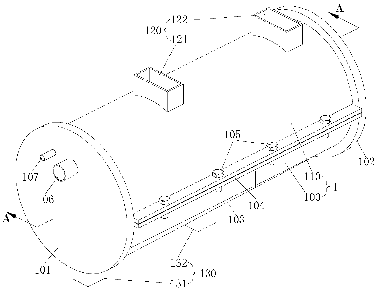
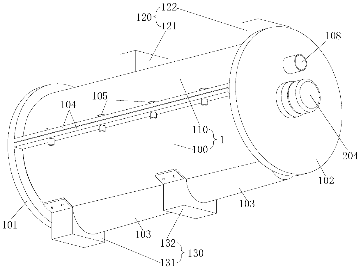
[0040] This embodiment relates to a gas treatment device, which can prolong the service life of the filter material in the gas treatment device, thereby reducing the cost of gas treatment and purification. The gas treatment device has a cavity formed by a casing and a filter unit arranged in the cavity, and the two ends of the casing are respectively provided with an air inlet and an exhaust for gas to enter and exit the cavity. port, the filter unit is driven to be rotatably separated between the air inlet and the exhaust port; the cavity is not fully filled with treatment liquid, and the filter unit is partially flushed by the treatment liquid In the middle; above the liquid level of the treatment liquid, a channel for the gas to flow through is formed; the gas passes through the filter unit soaked with the treatment liquid on the way of flowing through; because the filter unit The interception and / or the action of the treatment liquid constitutes the removal and separation ...

Embodiment 2

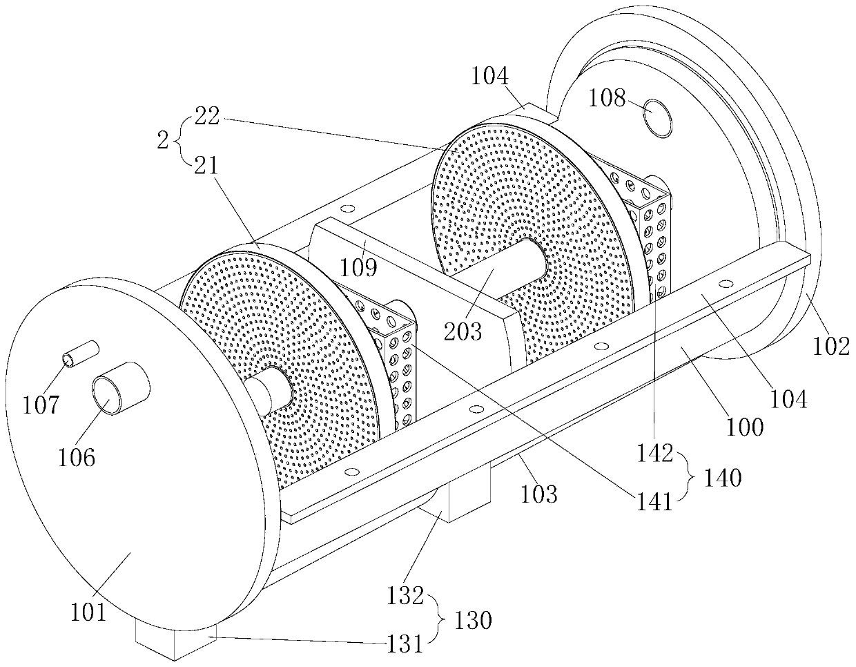
[0057] The cross-sectional structure of another structural form of the gas processing device described in this embodiment is as follows: Image 6 As shown, the housing 1 of the device is a cavity of a separate chamber, and a first filter unit 21, a second filter unit 22, a third filter unit 23, and a fourth filter unit 24 are sequentially arranged along the flow direction of the gas. Each filter unit 2, the filter level of four filter units 2 is increased sequentially, for example, the mesh size can be increased from 5 mesh to 40 mesh; or different filter materials can be used to remove corresponding harmful substances.

[0058] A spray head 150 can be installed above the upstream side of the first filter unit 21 to realize the preliminary spraying and dust removal of the gas. For the gas that needs to be supplemented with oxygen to react with the treatment liquid easily, it can be installed on the gas inlet side plate 101 Add air supply holes 107 for supplementing air. Only ...


PUM


Abstract

The invention provides a gas treatment device. The gas treatment device is provided with a cavity defined by a shell and a filtering unit arranged in the cavity. A gas inlet and a gas outlet for gas to enter and exit from a cavity are formed in the two ends of the shell of the device respectively, and a filtering unit is driven to be rotationally separated between the gas inlet and the gas outlet;the cavity is filled with certain treating fluid, and the filtering unit is partially flushed in the treating fluid; a channel for gas to flow through is formed above the liquid level of the treatment liquid; the gas passes through the filtering unit soaked with the treatment liquid in the flowing process; due to the interception of the filtering unit and/or the action of the treatment liquid, harmful substances in the gas are removed. According to the gas treatment device, the service life of the filter material in the gas treatment device can be prolonged, so that the gas treatment and purification cost is reduced.

Description

technical field [0001] The invention relates to the technical field of gas treatment and purification, in particular to a gas treatment device. Background technique [0002] With the development of social industry, the impact of factory exhaust gas and automobile exhaust on the atmosphere is becoming more and more serious. Therefore, countries pay more and more attention to environmental protection, and the requirements for various exhaust gas and exhaust emissions continue to increase; whether it is factory or catering industry exhaust gas , or automobile exhaust, all need to firstly process the discharged gas containing harmful substances, and only after meeting certain index requirements can it be allowed to be discharged into the atmosphere. In some specific industries or environments that require higher air cleanliness, higher air purification treatment is required to meet the requirements of use. Therefore, gas treatment and purification technology has been deeply dev...

Claims


Application Information

Patent Timeline
IPC IPC(8): B01D50/00B01D46/00B01D46/12B01D53/04B01D53/78B01D53/92B01D53/50B01D53/56B01D53/60
CPCB01D46/12B01D53/78B01D53/92B01D53/60B01D53/56B01D53/502B01D46/0036B01D53/04B01D2251/304B01D2251/404B01D2251/606B01D2258/01B01D46/74B01D46/62B01D50/60
Inventor 马志浩
Owner 马志浩
Why Eureka
Try Eureka