
Third-shaft and fourth-shaft joint structure of SCARA robot and SCARA robot

A technology of robots and shaft joints, applied in the directions of manipulators, program-controlled manipulators, joints, etc., can solve the problems of insufficient space of the manipulator, difficulty in heat dissipation, reduction of transmission accuracy and transmission efficiency, etc.

Pending Publication Date: 2020-07-14
深圳市卓博机器人有限公司
View PDF0 Cites 2 Cited by
  • Summary
  • Abstract
  • Description
  • Claims
  • Application Information

AI Technical Summary

Problems solved by technology

[0004] 1. The compact setting makes installation and maintenance difficult;
[0005] 2. In the case of setting a small arm extension, there may be insufficient space for the three- and four-axis robotic arms, and it is impossible to arrange two motors in a limited space, because the length of the pitch line of the synchronous belt has international standards, and the compact arrangement At the same time as the three-axis and four-axis motors, there will be a problem that the synchronous belt lacks a suitable pitch line length, and the non-standard synchronous belt is not conducive to later replacement and maintenance;
[0006] 3. The transmission mode of the synchronous belt is a non-direct drive mode, which will reduce the transmission accuracy and transmission efficiency;
[0007] 4. For SCARA robots with small arms, in order to ensure the compactness of the robot, the motor, reducer, and brake need to be miniaturized, which increases the cost and makes it difficult to dissipate heat

Method used


Image

  • Third-shaft and fourth-shaft joint structure of SCARA robot and SCARA robot
  • Third-shaft and fourth-shaft joint structure of SCARA robot and SCARA robot
  • Third-shaft and fourth-shaft joint structure of SCARA robot and SCARA robot

Examples


Embodiment 1

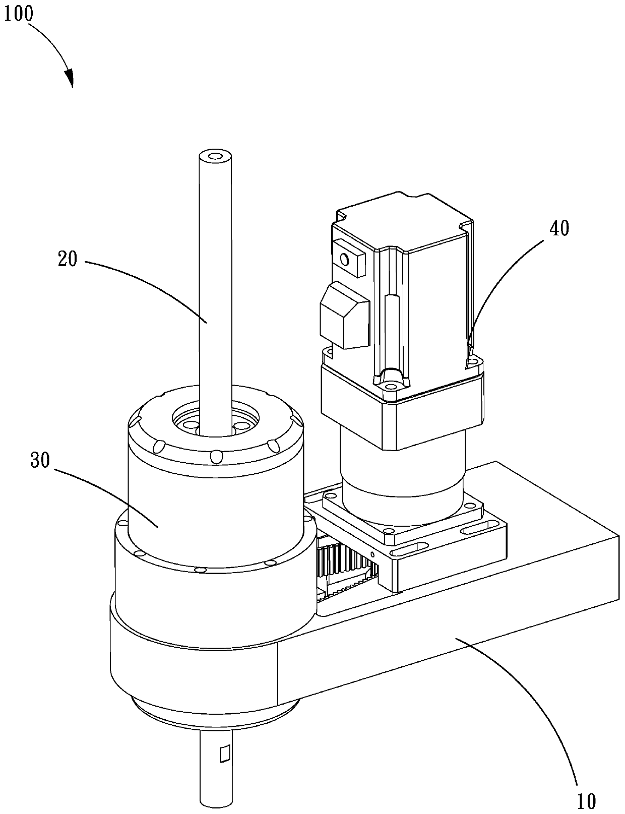
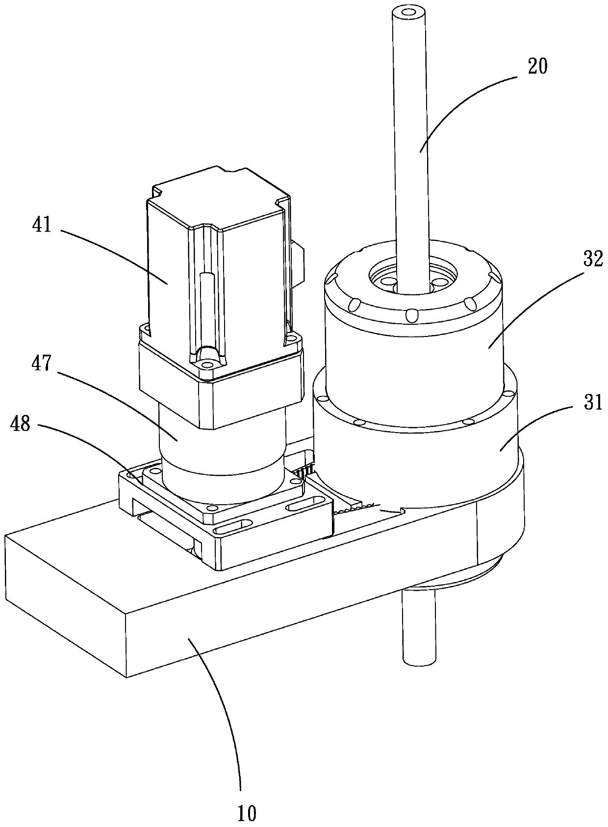
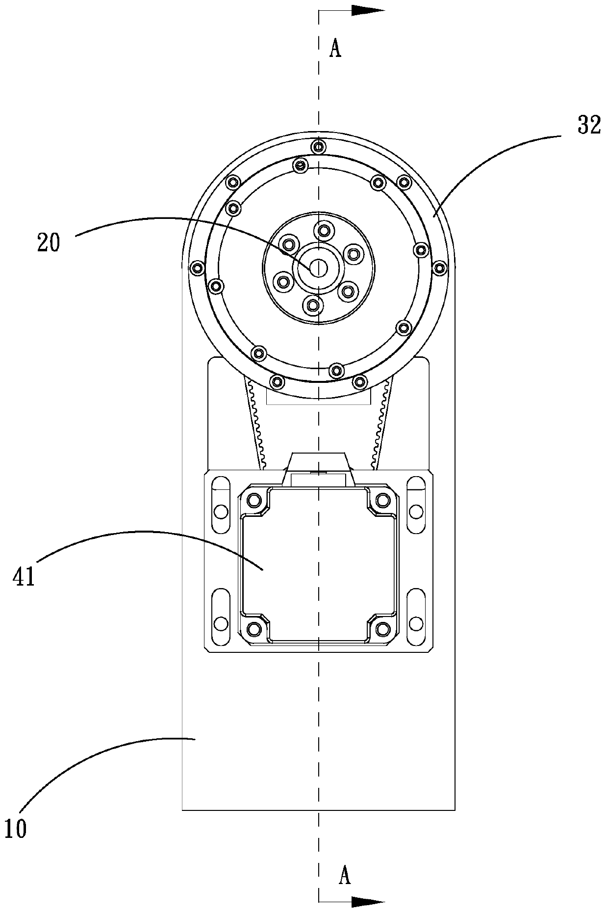
[0046] Such as Figure 1 to Figure 5 As shown, it is the three-axis and four-axis joint structure 100 of the SCARA robot according to the first embodiment of the present invention.

[0047] Such as Figure 1 to Figure 3 As shown, the three- and four-axis joint structure 100 of the SCARA robot includes: a second mechanical arm 10 , a ball spline shaft 20 vertically passing through the second mechanical arm 10 , and a second mechanical arm 10 installed on the second mechanical arm 10 The three-axis driving unit 30 and the fourth-axis driving unit 40 installed on the second mechanical arm 10 . Wherein, the second mechanical arm 10 is used to carry the ball spline shaft 20 , the third axis driving unit 30 , and the fourth axis driving unit 40 , and can be articulated with the first mechanical arm of the SCARA robot when in use. The ball spline shaft 20 is used to connect the gripper of the SCARA robot, and the ball spline shaft 20 can realize the screw structure required by the ...

Embodiment 2

[0066] Such as Figure 6 and Figure 7 As shown, it is the three-axis and four-axis joint structure 100 of the SCARA robot according to the second embodiment of the present invention.

[0067] The difference between the present embodiment and the first embodiment is that in the three- and four-axis joint structure 100 of the SCARA robot of the present embodiment, the third drive unit 30 is also provided with an encoder 36 connected to the direct drive motor 32 . The encoder 36 is ring-shaped as a whole and includes: a code disc shaft 361 connected to the motor shaft 322 , a hollow code disc 362 sleeved on the code disc shaft 361 , and a reading head mount 363 connected to the hollow code disc 362 . The code wheel shaft 361 is sleeved on the ball spline shaft 20 and extends from the central opening of the upper cover 352 to the outside. The hollow code wheel 362 is located at the part where the code wheel shaft 361 extends to the outside of the upper cover 352 , and the readi...


PUM


Abstract

The invention relates to a third-shaft and fourth-shaft joint structure of an SCARA robot. The third-shaft and fourth-shaft joint structure comprises a second mechanical arm, a ball spline shaft, a third shaft driving unit and a fourth shaft driving unit. The ball spline shaft is located at the executing end. The third shaft driving unit comprises a base and a direct drive motor. The direct drivemotor comprises a nut, a motor shaft, a rotor, a stator and a first bearing. The fourth-shaft driving unit comprises a servo motor, a driving belt wheel, a spline nut, a driven belt wheel, a synchronous belt and a second bearing. The invention further provides the SCARA robot. The installing and maintaining difficulty is lowered on the premise of keeping the integrated compactness, it is ensured that the robot is small and exquisite, the cost is lowered, and the heat dissipation capability is ensured. Under the condition of a small arm span, the requirement for the motor space layout of third-shaft and fourth-shaft mechanical arms is met, and the transmission precision and the transmission efficiency of the third shaft joint are improved.

Description

technical field [0001] The invention relates to the technical field of robot design, in particular to a three-axis and four-axis joint structure of a SCARA robot and a SCARA robot. Background technique [0002] SCARA (Selective Complaince Assembly Arm) robot is a special type of industrial robot with cylindrical coordinates. The SCARA robot has four axes and four degrees of freedom of motion, including translation along the X, Y, and Z directions and rotation around the Z axis. The third axis of the SCARA robot is a joint structure that realizes translation in the Z direction, generally called the Z axis. The fourth axis of the SCARA robot is a joint structure that realizes rotational motion around the Z axis, generally called the R axis. [0003] At present, the three-axis and four-axis transmission methods of SCARA robots on the market are mainly driven by synchronous belts, which require that the three-axis and four-axis motors are installed on the same mechanical arm o...

Claims


Application Information

Patent Timeline
Patent Type & Authority Applications(China)
IPC IPC(8): B25J9/04B25J9/10B25J9/12B25J17/00
CPCB25J9/04B25J9/10B25J9/12B25J17/00
Inventor 胡明陈汉辉
Owner 深圳市卓博机器人有限公司
Learn More