
Vehicle speed control method and device, vehicle electronic control equipment

A technology of vehicle speed control and deceleration control, which is applied in the direction of control devices, speed/acceleration control, vehicle components, etc., and can solve the problems of reducing emergency braking effect and sudden increase of vehicle speed

Active Publication Date: 2021-10-08
WEICHAI POWER CO LTD
View PDF6 Cites 0 Cited by
  • Summary
  • Abstract
  • Description
  • Claims
  • Application Information

AI Technical Summary

Problems solved by technology

[0004] Embodiments of the present invention provide a vehicle speed control method and device, and vehicle electronic control equipment, so as to at least solve the technical problem that the vehicle speed will suddenly increase and the emergency braking effect will be reduced when the vehicle is decelerated from a fixed deceleration to deceleration during emergency braking.

Method used


Image

  • Vehicle speed control method and device, vehicle electronic control equipment
  • Vehicle speed control method and device, vehicle electronic control equipment

Examples


Embodiment 1

[0028] According to an embodiment of the present invention, an embodiment of a vehicle speed control method is provided. It should be noted that the steps shown in the flow charts of the accompanying drawings can be executed in a computer system such as a set of computer-executable instructions, and, although in The flowcharts show a logical order, but in some cases the steps shown or described may be performed in an order different from that shown or described herein.

[0029] In the embodiment of the present invention, through the model predictive control algorithm, according to the current control input of the system and the future value of the historical information prediction process input, the feedback corrects the control input, scrolls and optimizes the performance index, smooths the deceleration demand in the entire early warning stage, and smoothly transitions to emergency control In the dynamic stage, it has the characteristics of prediction, fast response, rolling o...

Embodiment 2

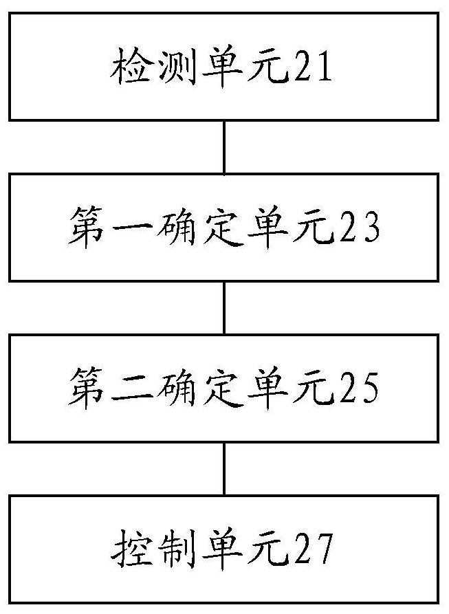
[0063] figure 2 is a schematic diagram of an optional vehicle speed control device according to an embodiment of the present invention, such as figure 2 As shown, the vehicle speed control device may include: a detection unit 21, a first determination unit 23, a second determination unit 25, and a control unit 27, wherein,


PUM


Abstract

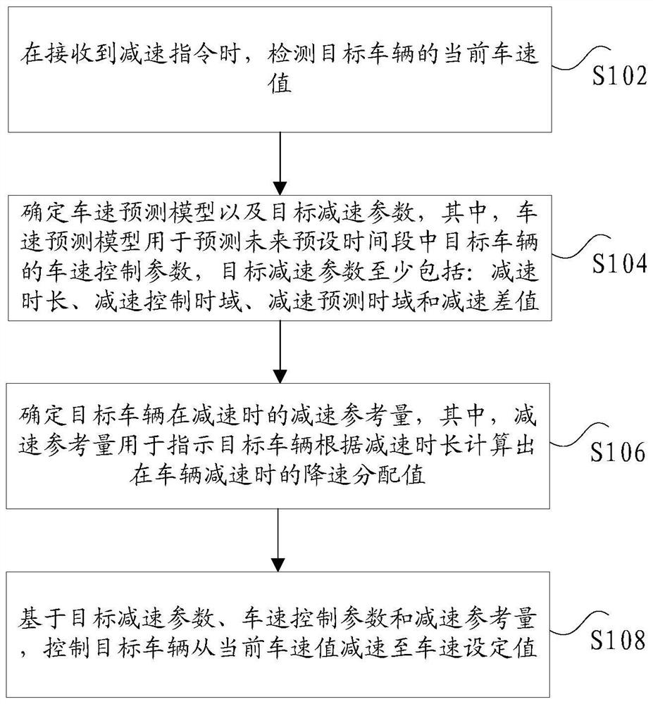
The invention discloses a vehicle speed control method and device, and vehicle electric control equipment. Wherein, the method includes: when receiving the deceleration command, detecting the current vehicle speed value of the target vehicle; determining the vehicle speed prediction model and the target deceleration parameters, wherein the vehicle speed prediction model is used to predict the vehicle speed control parameters of the target vehicle in the future preset time period , the target deceleration parameters at least include: deceleration time length, deceleration control time domain, deceleration prediction time domain and deceleration difference; determine the deceleration reference amount of the target vehicle during deceleration, wherein the deceleration reference amount is used to indicate that the target vehicle is calculated according to the deceleration time length The deceleration distribution value when the vehicle decelerates; based on the target deceleration parameter, the vehicle speed control parameter and the deceleration reference value, the target vehicle is controlled to decelerate from the current vehicle speed value to the vehicle speed set value. The invention solves the technical problem that when the vehicle is in emergency braking, the sudden increase in vehicle speed will be caused by the fixed deceleration until the deceleration is performed, reducing the emergency braking effect.

Description

technical field [0001] The invention relates to the technical field of vehicle speed control, in particular to a vehicle speed control method and device, and vehicle electronic control equipment. Background technique [0002] In the related technology, the automatic emergency braking system of the vehicle can decelerate during the warning stage, but the regulations require that the deceleration should not exceed 15km / h. Most of the current deceleration strategies are to decelerate with a fixed deceleration value when the warning is triggered. If the deceleration exceeds 15km / h The brakes are fully released at hour h. If the emergency braking trigger threshold has not been reached at this time, a control "vacuum zone" will appear in the transitional working conditions of these two stages. In some cases, the vehicle speed will increase suddenly, reducing the emergency braking stage. braking effect. [0003] For the above problems, no effective solution has been proposed yet. ...

Claims


Application Information

Patent Timeline
Patent Type & Authority Patents(China)
IPC IPC(8): B60W30/18B60K31/00
CPCB60K31/00B60W30/18109B60W2720/10
Inventor 马强张香平王学鹏代尚猛王龙晓
Owner WEICHAI POWER CO LTD
Learn More