
Installation bracket for outdoor electrical equipment

A technology for power equipment and mounting brackets, which is applied to mechanical equipment, machines/brackets, supporting machines, etc. It can solve the problems of inconvenient installation and operation, the inability to adjust the angle of the mounting bracket, and change the angle, so as to achieve the effect of convenient installation and adjustment

Pending Publication Date: 2020-07-14
杭州粒合信息科技有限公司
View PDF0 Cites 2 Cited by
  • Summary
  • Abstract
  • Description
  • Claims
  • Application Information

AI Technical Summary

Problems solved by technology

[0002] At present, the installation of outdoor power equipment basically uses simple hoops or hook holes for hanging installation. Most of the outdoor equipment is installed in a closed sheet metal box, and less is installed with a bracket after reaching the waterproof level. And the existing outdoor power equipment The installation bracket has the defect of being unable to adjust the angle. Once it is installed, it will be fixed. At the same time, the existing outdoor power equipment installation bracket cannot be self-adapted to the horizontal bar or vertical bar in the same bracket. It is not convenient for installation and operation. Change the angle arbitrarily according to your needs

Method used


Image

  • Installation bracket for outdoor electrical equipment
  • Installation bracket for outdoor electrical equipment
  • Installation bracket for outdoor electrical equipment

Examples


Embodiment Construction

[0040] The following will clearly and completely describe the technical solutions in the embodiments of the present invention with reference to the accompanying drawings in the embodiments of the present invention. Obviously, the described embodiments are only some, not all, embodiments of the present invention.

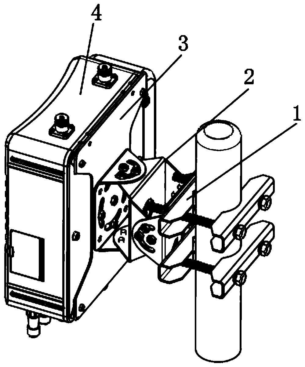
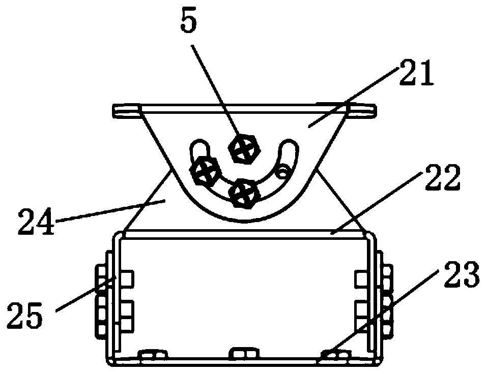
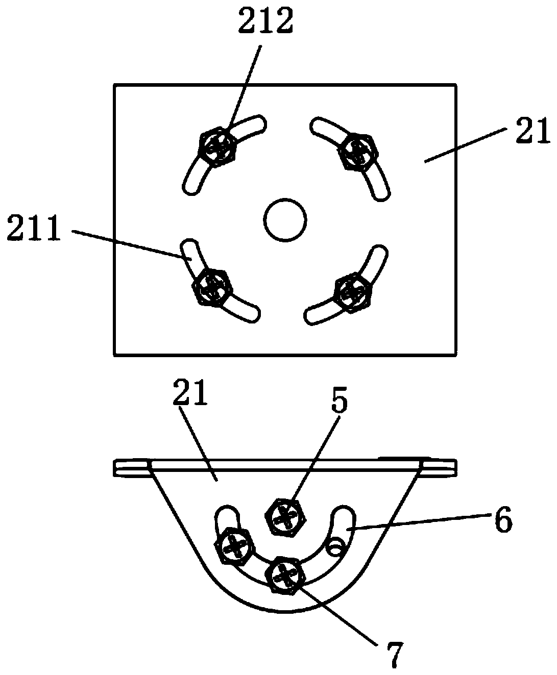
[0041] Such as Figure 1-3 As shown, a mounting bracket for outdoor power equipment includes: a caliper assembly 1, a universal rotation assembly 2 and an equipment mounting plate 3;

[0042] The caliper assembly 1 is connected to one end of the universal rotation assembly 2, and the other end of the universal rotation assembly 2 is connected to the equipment mounting plate 3, and the outside of the equipment mounting plate 3 is fixed with an electric device 4;

[0043] The caliper assembly 1 is fixed on the outdoor installation pole, and the direction of the caliper assembly 1 can be adjusted through the universal rotation assembly 2 .

[0044] The universal rotati...


PUM


Abstract

The invention discloses an installation bracket for outdoor electrical equipment. The installation bracket comprises a caliper assembly, a universal rotation assembly and an equipment installation plate, and the caliper assembly is connected with one end of the universal rotation assembly. According to the installation bracket, a pitching adjusting frame and a left-right adjusting frame in the universal rotation assembly can adjust the angle of the electrical equipment after the electrical equipment is installed, after adjusting is completed, self locking is conducted through limiting screw and limiting screw holes, meanwhile, connection studs connected between the pitching adjusting frame and the left-right adjusting frame are connected by adopting arc-shaped grooves, thus, the connectionstuds can be rotationally adjusted in the arc-shaped grooves, it is achieved that the electrical equipment on the equipment installation plate is subjected to circumferential rotation adjusting, andthe difficulty that onsite installation personnel need to adjust the posture of the equipment is reduced; and in addition, posture adjustment can be conducted on the equipment according to the actualoutdoor electrical equipment communication effect, so that the installation bracket for the outdoor electrical equipment is more convenient to use when the electrical equipment is installed and adjusted.

Description

technical field [0001] The invention relates to the technical field of power equipment installation brackets, in particular to an outdoor power equipment installation bracket. Background technique [0002] At present, the installation of outdoor power equipment basically uses simple hoops or hook holes for hanging installation. Most of the outdoor equipment is installed in a closed sheet metal box, and less is installed with a bracket after reaching the waterproof level. And the existing outdoor power equipment The installation bracket has the defect of being unable to adjust the angle. Once it is installed, it will be fixed. At the same time, the existing outdoor power equipment installation bracket cannot be self-adapted to the horizontal bar or vertical bar in the same bracket. It is not convenient for installation and operation. Change the angle arbitrarily according to your needs. Contents of the invention [0003] The object of the present invention is to propose a ...

Claims


Application Information

Patent Timeline
IPC IPC(8): F16M11/02F16M11/12F16M13/02
CPCF16M11/02F16M11/12F16M13/02
Inventor 王波戴翚周闯
Owner 杭州粒合信息科技有限公司
Learn More