Laser radar optical system and laser radar

A laser radar and optical system technology, applied in the field of measuring instruments, can solve the problems of limiting the vertical spatial resolution of laser radar, difficulty in compressing the system space, and increasing the difficulty of processing, etc., to achieve improved vertical spatial resolution, small intervals, and low manufacturing difficulty Effect

Pending Publication Date: 2020-07-14
武汉天眸光电科技有限公司
View PDF0 Cites 6 Cited by
  • Summary
  • Abstract
  • Description
  • Claims
  • Application Information

AI Technical Summary

Problems solved by technology

[0003] In order to improve the vertical spatial resolution of LiDAR, currently the most adopted methods are as follows: (1) Reducing the arrangement interval of lasers on a single launch board. However, when multiple lasers are integrated on one launch There needs to be a preset pointing angle between them, so interference is likely to occur during the production process, which increases the difficulty of processing, limits the lower limit of the laser arrangement interval, and thus limits the vertical spatial resolution of the laser radar; (2) the multi- Two emitting boards are placed side by side and misplaced in height, and the distance between lasers is reduced by displacing the height of lasers. In this way, it will be difficult to realize installation and debugging in a given space, and it is also difficult to compress the system space.
As far as the current technology is concerned, it is difficult to have a simplified way to improve the vertical spatial resolution of lidar

Method used


Image

  • Laser radar optical system and laser radar
  • Laser radar optical system and laser radar
  • Laser radar optical system and laser radar

Examples


Embodiment Construction

[0032] The following will clearly and completely describe the technical solutions in the embodiments of the present invention with reference to the accompanying drawings in the embodiments of the present invention. Obviously, the described embodiments are only part of the embodiments of the present invention, not all of them. Based on the embodiments of the present invention, all other embodiments obtained by persons of ordinary skill in the art without creative efforts fall within the protection scope of the present invention.

[0033] It should be noted that if there is a directional indication (such as up, down, left, right, front, back...) in the embodiment of the present invention, the directional indication is only used to explain the position in a certain posture (as shown in the accompanying drawing). If the specific posture changes, the directional indication will also change accordingly.

[0034] In addition, if there are descriptions involving "first", "second" and ...


PUM


Abstract

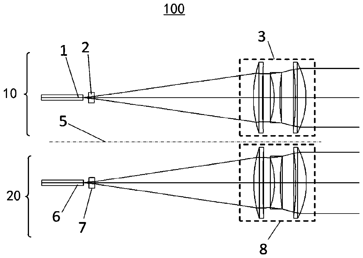
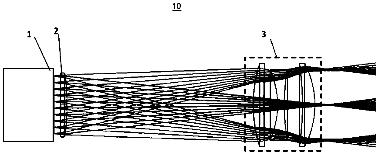
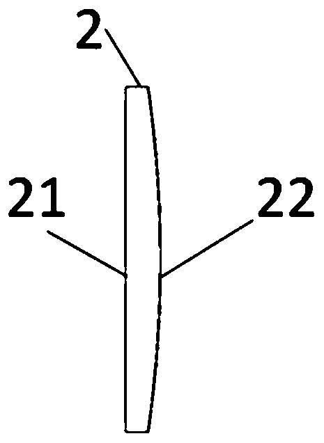
The invention discloses a laser radar optical system and a laser radar, which relates to the technical field of measuring instruments. The laser radar optical system comprises a transmitting system and a receiving system, wherein the transmitting system sequentially comprises a laser light source, a correction lens group and a collimating lens group along the light transmission direction; the laser light source is used for transmitting a plurality of light beams, the correction lens group comprises at least one correction lens, and the correction lens is used for correcting the plurality of light beams emitted by the laser light source, so that the central axis of each light beam is aligned with the entrance pupil center of the collimating lens group. The invention aims to provide the simple and good-effect laser radar optical system to improve the vertical spatial resolution of the laser radar.

Description

technical field [0001] The invention relates to the technical field of measuring instruments, in particular to a laser radar optical system and a laser radar. Background technique [0002] At present, mechanical lidar is one of the most effective ways to realize the stability of automatic driving. Multiple lasers and photodetectors are used to realize multi-channel signal detection. Different height positions of the plane to achieve preset vertical viewing angles. [0003] In order to improve the vertical spatial resolution of LiDAR, currently the most adopted methods are as follows: (1) Reducing the arrangement interval of lasers on a single launch board. However, when multiple lasers are integrated on one launch There needs to be a preset pointing angle between them, so interference is likely to occur during the production process, which increases the difficulty of processing, limits the lower limit of the laser arrangement interval, and thus limits the vertical spatial r...

Claims


Application Information

Patent Timeline
Patent Type & Authority Applications(China)
IPC IPC(8): G01S7/481G01S7/484G01S7/4911
CPCG01S7/4815G01S7/484G01S7/4911
Inventor 程刚刘娟娟
Owner 武汉天眸光电科技有限公司
Why Eureka
Try Eureka