
Blast furnace hot blast stove gas pipe network coordinated furnace changing method

A technology of gas pipe network and hot blast stove, which is applied to blast furnaces, blast furnace details, blast furnace parts, etc., can solve problems such as manpower management costs and untimely communication, uncertain blast furnace status, and non-prospective furnace replacement operations, etc., to achieve relief Effects of pressure fluctuations in the gas pipeline network, reduction of pressure fluctuations, and reduction of overlapping furnace replacement time

Active Publication Date: 2020-07-14
北京和隆优化科技股份有限公司
View PDF10 Cites 1 Cited by
  • Summary
  • Abstract
  • Description
  • Claims
  • Application Information

AI Technical Summary

Problems solved by technology

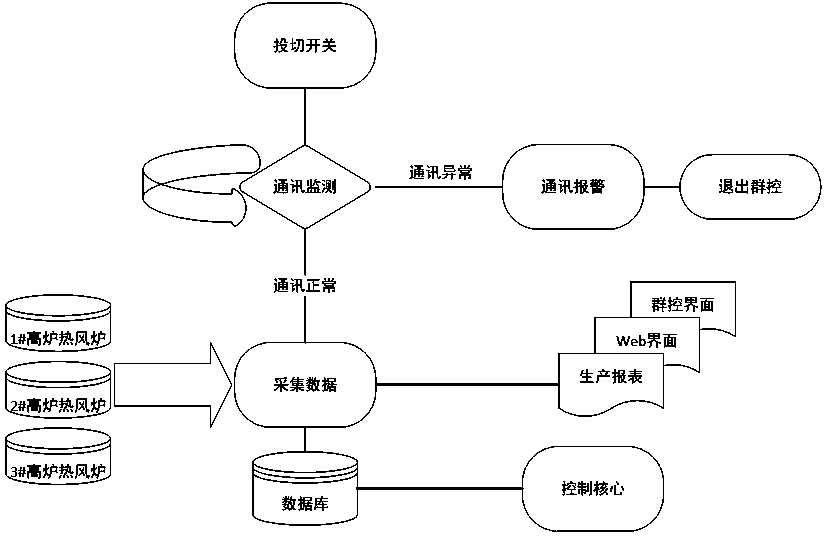
[0003] At present, the management mode of hot blast stove gas pipeline network usually adopts manual command operation, communicates the current status of each blast furnace hot blast stove operation room by calling, and asks the coordination center whether the furnace replacement condition is available when changing the furnace, and the entire coordinated furnace replacement process is manually judged and complete, and the changeover operation is not proactive
The uncertain status of blast furnaces, manpower management costs and untimely communication are the biggest problems of this governance method

Method used


Image

  • Blast furnace hot blast stove gas pipe network coordinated furnace changing method
  • Blast furnace hot blast stove gas pipe network coordinated furnace changing method
  • Blast furnace hot blast stove gas pipe network coordinated furnace changing method

Examples


Embodiment Construction

[0018] The present invention will be described in detail below in conjunction with the accompanying drawings and embodiments.

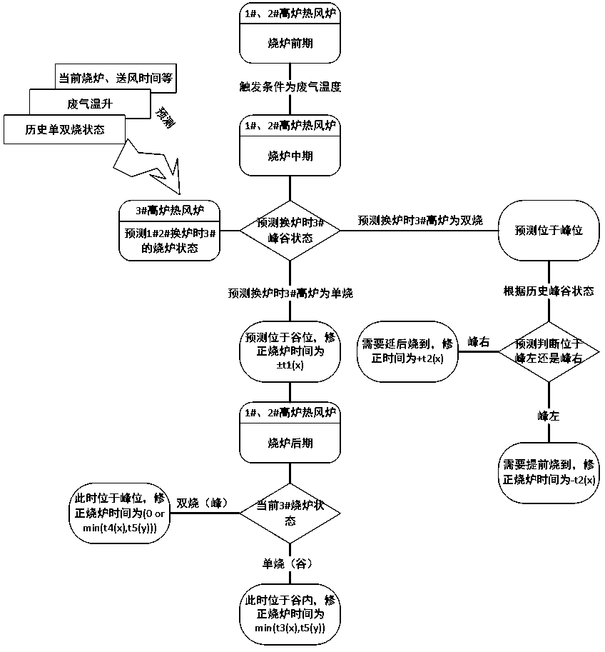
[0019] Taking a blast furnace hot blast stove site as an example, 3# is a 3200m³ blast furnace hot blast stove with two firings and two delivery, 1# and 2# are 1880m³ blast furnace hot blast stove with one firing, one braising and one delivery, and the comparison of the firing time of the 3# blast furnace hot blast stove The fixed time is about 90 minutes, the furnace replacement time (single firing time) is about 30 minutes, and the air supply time is about 120 minutes. 1# and 2# blast furnace hot blast stoves are fired according to the exhaust gas temperature, and the exhaust gas is burned to between 375°C and 395°C. For intermittent furnace replacement, the basic firing time is between 55 minutes and 65 minutes. Due to the firing mode of one firing, one stewing and one delivery, the furnace replacement time (double firing time) is between 1 minute a...


PUM


Abstract

The invention relates to the technical field of blast furnace hot blast stove changing time coordination control, and discloses a method for coordinating the furnace changing time between blast furnace hot blast stoves based on blast furnace hot blast stove burning state and future state estimation. The method comprises the steps of establishing an optical fiber physical link between a server anda blast-furnace hot-blast stove; collecting operation parameter data of each blast furnace hot blast stove; judging the running state of each blast furnace hot blast stove in real time; in the middlestage of furnace burning, according to the furnace burning state of each hot blast stove, predicting the furnace changing time of each hot blast stove, correcting the strength of each hot blast stovein advance according to the prediction result, and in the last stage of furnace burning, according to the furnace burning and furnace changing conditions of each hot blast stove, adjusting the furnacechanging time of each hot blast stove within the adjustable interval of the exhaust gas temperature. According to the method, furnace changing coordination among the multiple hot blast stoves is achieved through advanced medium-term furnace burning strength change and accurate control over the last-stage furnace changing opportunity, overlapping furnace changing is avoided to the maximum extent,pressure fluctuation of a gas pipe network is reduced, and a foundation is laid for balance control over the pipe network.

Description

technical field [0001] The invention relates to the field of coordinated control of gas pipe networks of metallurgical blast furnace hot blast stoves, in particular to a method for coordinated replacement of gas pipe networks of blast furnace hot blast stoves. Background technique [0002] In the metallurgical industry, the hot blast stove is one of the main supporting equipment for the blast furnace in the ironworks. Its function is to continuously provide high-temperature hot air above 1000 degrees for the blast furnace. , Two burning and one sending, one burning and two sending, cross-parallel and other air supply systems. Blast furnace hot blast stoves in the metallurgical industry are one of the main users of blast furnace gas. The amount of blast furnace gas used by hot blast furnaces in various iron and steel metallurgical plants accounts for 30% to 60% of the total blast furnace gas production. The air volume process belongs to the periodic heat storage and heat rel...

Claims


Application Information

Patent Timeline
Patent Type & Authority Applications(China)
IPC IPC(8): G05D23/20C21B9/14
CPCC21B9/14G05D23/20
Inventor 李明党李智良
Owner 北京和隆优化科技股份有限公司
Learn More