Capacitive touch sensing circuit

A technology of capacitive touch and detection circuit, which is applied in the field of touch detection, can solve the problems of difficulty in reducing production cost, noise amplification, large chip area, etc. Effect of Die Area

Pending Publication Date: 2020-07-14
RAYDIUM SEMICON
View PDF5 Cites 0 Cited by
  • Summary
  • Abstract
  • Description
  • Claims
  • Application Information

AI Technical Summary

Problems solved by technology

[0005] The disadvantage of the general self-capacitance touch detection is that the smaller the parallel capacitor Cop is, the greater the change of the detectable potential and the easier it is to detect, but it will also amplify the noise relatively.
Once the output is saturated due to noise, even if the detection capacitor Cb changes, the output cannot be affected, and the change of the detectable potential will be invalid
Therefore, the shunt capacitor Cop usually has a capacitance value of several pF or more, which occupies a relatively large chip area, resulting in that the chip area cannot be effectively reduced and the production cost is difficult to reduce.

Method used


Image

  • Capacitive touch sensing circuit
  • Capacitive touch sensing circuit
  • Capacitive touch sensing circuit

Examples


Embodiment Construction

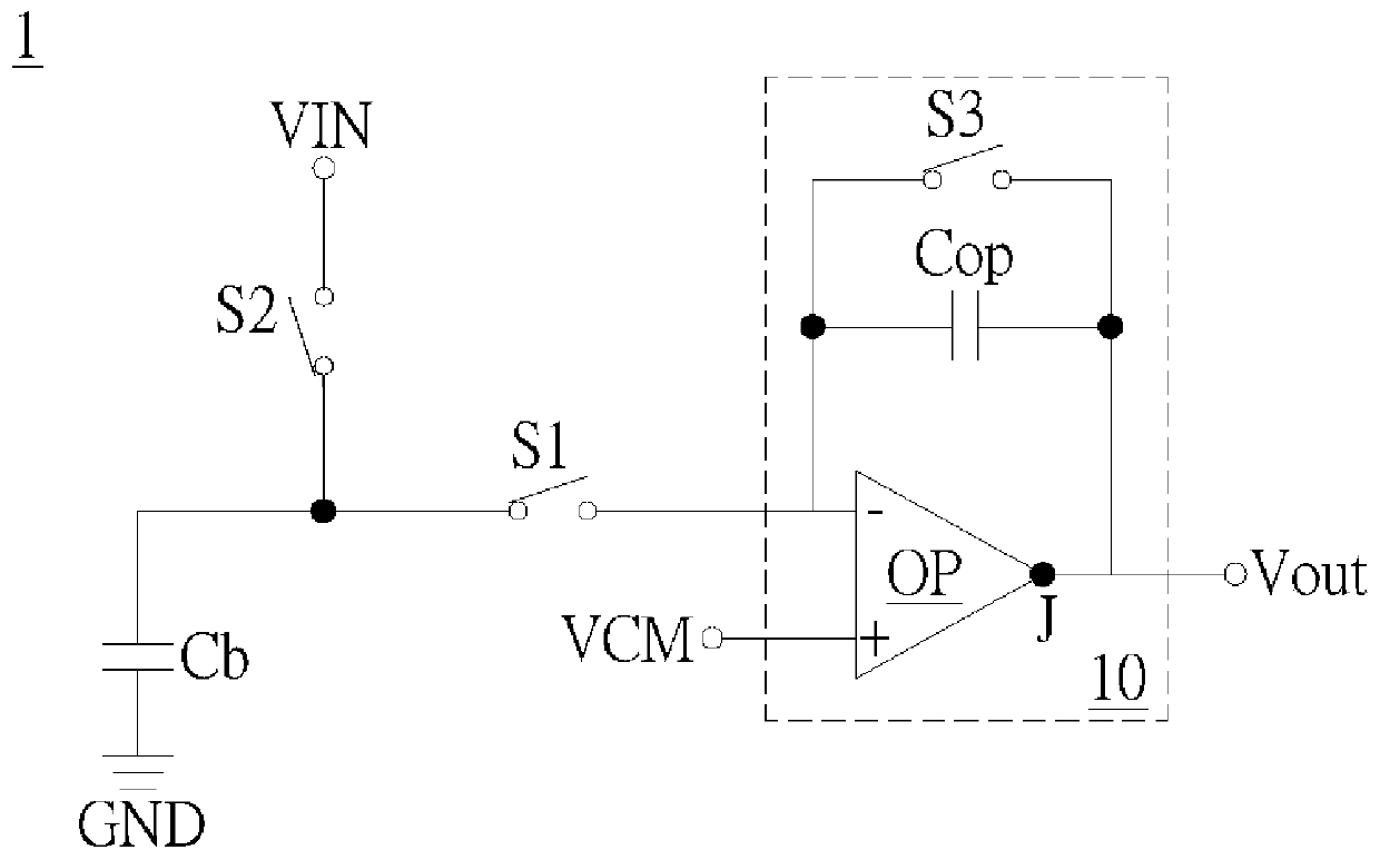
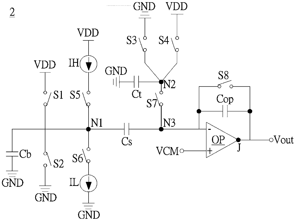
[0058] A specific embodiment according to the present invention is a capacitive touch detection circuit. In this embodiment, the capacitive touch detection circuit is a self-capacitive touch detection circuit, but not limited thereto.

[0059] Please refer to figure 2 , figure 2 This is a schematic diagram of the capacitive touch detection circuit 2 in this embodiment.

[0060] like figure 2 As shown, the capacitive touch detection circuit 2 may include an operational amplifier OP, a parallel capacitor Cop, a serial capacitor Cs, a detection capacitor Cb, a test capacitor Ct, a first switch S1, a second switch S2, and a third switch S3 , the fourth switch S4, the first current source IH, the second current source IL, the fifth switch S5, the sixth switch S6, the seventh switch S7 and the eighth switch S8.

[0061] The operational amplifier OP has a first input terminal −, a second input terminal + and an output terminal J. Wherein, the first input terminal − is coupled...


PUM


Abstract

A capacitive touch sensing circuit comprises an operational amplifier, a parallel capacitor, a series capacitor, a detection capacitor, a test capacitor, first to eighth switches, a first current source and a second current source. A parallel capacitor is coupled to a first input terminal and an output terminal of an operational amplifier. A series capacitor and a sensing capacitor are coupled inseries between first input terminal and ground. A test capacitor is coupled to a second node and ground. A first switch is coupled to an operating voltage and a first node. A second switch is coupledto first node and ground. A third switch is coupled to second node and ground. A fourth switch is coupled to operating voltage and second node. A first current source and a fifth switch are coupled between operating voltage and first node. A sixth switch and a second current source are coupled between first node and ground. A seventh switch is coupled to second node and a third node. An eighth switch is coupled to the parallel capacitor.

Description

technical field [0001] The invention relates to touch detection, in particular to a capacitive touch detection circuit. Background technique [0002] Such as figure 1 As shown, in the self-capacitance touch detection circuit 1, during the charging phase, the switch S1 is turned off and the switch S2 is turned on, so that one end of the detection capacitor Cb is coupled to the input voltage VIN; S2 is turned off and the switch S1 is turned on, so that one end of the detection capacitor Cb is coupled to the switched capacitor circuit 10 . [0003] The switched capacitor circuit 10 includes an operational amplifier OP, a shunt capacitor Cop and a switch S3. The parallel capacitor Cop and the parallel capacitor Cop are coupled in parallel between the first input terminal − and the output terminal J of the operational amplifier OP. The second input terminal + of the operational amplifier OP is coupled to the reference voltage VCM, so that the potential of one terminal of the d...

Claims


Application Information

Patent Timeline
Patent Type & Authority Applications(China)
IPC IPC(8): G06F3/041G06F3/044
CPCG06F3/0418G06F3/044H03K17/962H03K2217/960705H03K2217/960725G06F3/04166G06F3/04182H03K2217/96015H03K2017/9609
Inventor 张智凯陈治雄光宇许有津
Owner RAYDIUM SEMICON
Why Eureka
Try Eureka