Shunt resistor

A technology of shunt resistors and resistors, applied in the direction of resistors, resistor parts, non-adjustable metal resistors, etc., can solve the problem that the base metal cannot obtain sufficient joint strength, and achieve strong welding, improved load-bearing capacity, and easy dissolution Effect

Active Publication Date: 2020-07-14
SANCALL
View PDF12 Cites 0 Cited by
  • Summary
  • Abstract
  • Description
  • Claims
  • Application Information

AI Technical Summary

Problems solved by technology

[0003] However, the voltage detection terminal of the above-mentioned conventional shunt resistor h

Method used


Image

  • Shunt resistor
  • Shunt resistor
  • Shunt resistor

Examples


Embodiment Construction

[0029] An embodiment of the shunt resistor of the present invention will be specifically described below with reference to the drawings. In addition, in the following description, when showing the up, down, left, and right directions, the up, down, left, and right sides when viewed from the front of the illustrations shall prevail.

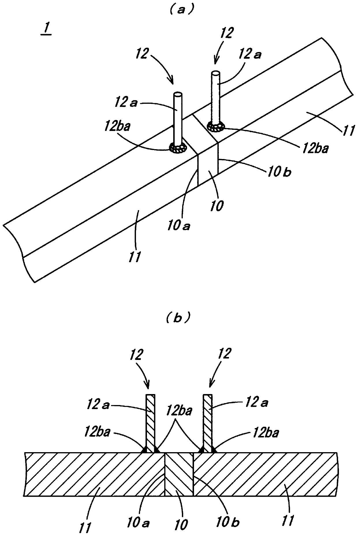
[0030] The shunt resistor of this embodiment is especially used to measure the flow from the battery to the motor in high-voltage applications used in electric vehicles (EV vehicles), hybrid vehicles (HV vehicles), plug-in hybrid vehicles (PHV vehicles), etc. The current value of the current path through which the large current of the circuit flows, such as figure 1 (a), figure 1 As shown in (b), the shunt resistor 1 is composed of a resistor body 10, a pair of base materials 11 sandwiching the resistor body 10 and integrally formed with the resistor body 10, and a measurement terminal 12 fixed to the base material 11. constitute. Resistor 10 i...


PUM


Abstract

The objective of the present invention is to provide a shunt resistor with which it is possible to obtain adequate joint strength. The present invention has: a resistor 10; a pair of base members 11 sandwiching the resistor 10 and formed integrally with the resistor 10; and measurement terminals 12 secured to the base members 11, each measurement terminal 12 having a shaft part 12a, and a projecting part projecting integrally from the tip-end side of the shaft part 12a, the projecting part being dissolved using an electrical resistance welding machine, and thereby becoming a welding material 12ba. The measurement terminals 12 are thereby secured to the base members 11.

Description

technical field [0001] The present invention relates to a shunt resistance, especially for measuring high voltage applications from electric vehicles (EV vehicles), hybrid vehicles (HV vehicles), plug-in hybrid vehicles (PHV vehicles) etc. A shunt resistor used to determine the current value of the current path through which a large current flows from the battery to the motor circuit. Background technique [0002] As a conventional shunt resistor, there is known a shunt resistor described in Patent Document 1 (JP-A-2017-009419). In this shunt resistor, through-holes are respectively formed in two plate-shaped base materials that sandwich the resistor body and are formed integrally with the resistor body, and the first terminal part is inserted into the through-hole, and is connected from the through-hole. Protrude the voltage detection terminal of the second terminal part. [0003] However, the voltage detection terminal of the above conventional shunt resistor has a probl...

Claims


Application Information

Patent Timeline
IPC IPC(8): H01C13/00G01R15/00H01C1/144
CPCH01C1/144G01R1/203H01C7/06H01C7/20
Inventor 村上建二
Owner SANCALL
Why Eureka
Try Eureka