Wearable electronic equipment
An electronic device and electrode technology, which is applied in the field of wearable electronic devices, can solve the problems of low detection accuracy of wearable electronic devices and poor skin fit, so as to increase the area, eliminate common mode interference, and reduce contact impedance. Effect
Inactive Publication Date: 2020-07-17
SHENZHEN GOODIX TECH CO LTD
7 Cites 3 Cited by
AI-Extracted Technical Summary
Problems solved by technology
But these two electrodes are often poorly fitted to the skin of the measured object, especially when the measured o...
Method used
For the problems referred to above, the application increases the effective contact area of the first electrode and the second electrode and the skin of the measured object by increasing the area of the first electrode and the second electrode, so that the first electrode and the second electrode The electrodes are in good contact with the skin of the measured object, thereby improving the detection accuracy.
[0046] In the embodiment of the present application, the first electrode and the second electrode are extended from the bottom of the body to the connecting strip, and the first electrode includes a first contact end arranged at the bottom of the body and a first contact end arranged on the first connecting strip. Three contact ends, the second electrode includes a second contact end arranged on the bottom of the body and a fourth contact end arranged on the second connection strip, thereby increasing the area of the first electrode and the second electrode, so that the first electrode and the second electrode The second electrode is in good contact with the skin of the measured object. The first electrode has good contact with the skin of the measured object, which reduces the contact impedance formed between the first electrode and the skin of the measured object, increases the amplitude of the ECG signal collected by the first electrode and reduces noise interference, the accuracy of the ECG signal collected by the first electrode has an order of magnitude improvement compared with the ECG signal detected by the existing wearable electronic device, thereby improving the detection accuracy; and the first electrode is arranged at the bottom of the body The electrocardiographic signals collected by the contact end and the contact end arranged on the connection belt can compensate each other, so that the first electrode can stably collect high-quality electrocardiographic signals, even when the wearable electronic device is in contact with the measured object. In the case of poor skin contact, even in a state of motion, the first electrode can still stably collect high-quality ECG signals, thereby improving the detection stability of the wearable electronic device. The second electrode is in good contact with the skin of the measured object, so that the second electrode can feed back the common-mode signal to the detection circuit to eliminate common-mode interference in the detection circuit, thereby improving detection accuracy.
[0062] In the embodiment of the present application, by extending the first electrode and the second electrode from the bottom of the body to the connected strip, the area of the first electrode and the second electrode is increased, so that the first electrode and the second electrode Good contact with the skin of the measured object increases the amplitude of the ECG signal collected by the first electrode and reduces noise interference, and the second electrode can feed back the magnitude of the common-mode signal to the detection circuit to eliminate the detection The interference of the common mode signal in the circuit improves the accuracy of ECG detection; and the first electrode and the second electrode are symmetrically distributed about the central axis of the bottom of the body, which makes the first electrode and the second electrode easier to realize in the process, and the appearance It is more beautiful; in addition, the ECG signals collected by the contact end of the first electrode set on the bottom of the body and the contact end of the connecting belt can compensate each other, so the first electrode can stably co...
Abstract
The invention provides electronic equipment. The wearable electronic equipment comprises a body, a first connecting belt and a second connecting belt, and the first connecting belt and the second connecting belt are correspondingly connected with the two sides of the body; the body comprises a first contact end and a second contact end which are arranged at the bottom of the body; the first connecting belt comprises a third contact end arranged on the first connecting belt, the third contact end electrically communicates with the first contact end to form a first electrode, and the first electrode is used for being in contact with a measured object; the second connecting belt comprises a fourth contact end arranged on the second connecting belt, the fourth contact end electrically communicates with the second contact end to form a second electrode, and the second electrode is used for being in contact with the measured object; and the wearable electronic equipment further comprises a third electrode, and the wearable electronic equipment obtains the electrocardiac information of the measured object through the first electrode, the second electrode and the third electrode. Accordingto the wearable electronic equipment, the accuracy of electrocardiac detection can be improved.
Application Domain
Diagnostic recording/measuringSensors
Technology Topic
PhysicsWearable Electronic Device +4
Image
Examples
- Experimental program(1)
Example Embodiment
[0033] The technical solutions of the present invention will be clearly and completely described below in conjunction with the accompanying drawings. Obviously, the described embodiments are part of the embodiments of the present invention, rather than all of them. Based on the embodiments of the present invention, all other embodiments obtained by those of ordinary skill in the art without creative work shall fall within the protection scope of the present invention.
[0034] The principle of detecting ECG information is that when the heart contracts and relaxes, there is a small amount of bioelectricity, which will cause a series of potential changes, which can be transmitted to the body surface through biological tissues. The ECG signals of different parts of the body surface of the measured object are collected, and the ECG information of the measured object can be obtained according to the ECG signals. In practical applications, electrodes are usually set on at least three parts of the body surface of the object to be measured. The ECG signal of the object can be collected through the electrodes, and then the ECG information of the object to be measured is calculated based on the ECG signal. .
[0035] figure 1 It is a cross-sectional view of a typical wearable electronic device. Such as figure 1 As shown, the wearable electronic device 10 includes a main body 11, a first connecting strap 12 and a second connecting strap 13, and the first connecting strap 12 and the second connecting strap 13 are respectively connected to two sides of the main body 11. The body 11 includes a first electrode 111, a second electrode 112, a first connection part 113, a second connection part 114, a PCB circuit board 115 and a battery 116. The first electrode 111 and the second electrode 112 are arranged at the bottom of the body 11. The first electrode 111 and the second electrode 112 are in electrical contact with the first connection portion 113 and the second connection portion 114, respectively. The first connection portion 113 and the second connection portion The parts 114 are electrically connected to the PCB circuit board 115, so the first electrode 111 and the second electrode 112 are electrically connected to the PCB circuit board 115; the body 11 also includes a third electrode (not shown in the figure), the third electrode It can be arranged on the side of the body 11 and is electrically connected to the PCB circuit board 115; the PCB circuit board 115 is provided with a chip (not shown in the figure) that can be used for ECG detection, and the chip passes through the first electrode 111 and the second electrode 111. The electrode 112 and the third electrode calculate and obtain the ECG information of the measured object; the battery 116 is connected to the PCB circuit board 115, and the battery 116 is used to provide power for the ECG detection circuit.
[0036] Exemplarily, the wearable electronic device 10 may be a smart watch, the main body 11 is the watch head of the smart watch, and the first connection band 12 and the second connection band 13 are two watch bands of the smart watch.
[0037] Exemplarily, the first electrode 111, the second electrode 112, the first connection portion 113, and the second connection portion 114 may be conductors such as metal parts, and the third electrode may be a metal button provided on the side of the body.
[0038] In a possible application scenario, when the wearable electronic device is worn on the left wrist of the subject, the first electrode 111 and the second electrode 112 provided on the bottom of the main body are in contact with each other on the left wrist of the subject. skin contact. When the right hand of the measured object touches the third electrode, the first electrode 111 and the third electrode collect the ECG signals of different parts of the measured object respectively, and the second electrode 112 is based on the first electrode 111 and the third electrode. The collected ECG signals are summed to obtain the size of the common mode signal, and the common mode signal is fed back to the detection circuit, thereby eliminating common mode interference in the detection circuit. The wearable electronic device 10 calculates and obtains the ECG information of the measured object according to the collected ECG signal.
[0039] In the process of collecting the ECG signals of different parts of the body surface of the measured object, the measured object is equivalent to a signal source, which forms a detection circuit together with the wearable electronic device. The internal resistance of the signal source includes the contact impedance formed by the electrode of the wearable electronic device and the skin of the object under test. When the contact impedance formed by the electrode of the wearable electronic device and the skin of the measured object is larger, the thermal noise of the contact impedance itself is also greater. At this time, the amplitude of the ECG signal collected by the electrode is smaller and more severe. Large noise interference will greatly reduce the detection accuracy of wearable electronic devices. In actual application scenarios, the first electrode and the second electrode provided at the bottom of the main body often have a poor fit with the skin of the object under test, that is, the first electrode and the second electrode and the skin of the object under test are often poorly fitted. Poor contact. At this time, the effective electrode area of the first electrode in contact with the skin of the measured object is small, resulting in a larger contact impedance between the first electrode and the skin of the measured object, and the amplitude of the ECG signal collected by the first electrode Small and large noise interference; In addition, the second electrode is not in good contact with the skin of the measured object, causing the second electrode to fail to feed back the common-mode signal to the detection circuit, thus failing to eliminate the common-mode signal interference in the loop Therefore, the first electrode and the second electrode have poor contact with the skin of the measured object, which reduces the accuracy of ECG detection. The poor contact of the first electrode and the second electrode provided at the bottom of the main body with the skin of the object to be measured is a pain point that leads to low accuracy of the ECG detection of the wearable electronic device.
[0040] In response to the above problems, the present application increases the effective contact area between the first electrode and the second electrode and the skin of the tested object by increasing the area of the first electrode and the second electrode, so that the first electrode and the second electrode are The skin of the test object is in good contact, thereby improving the detection accuracy.
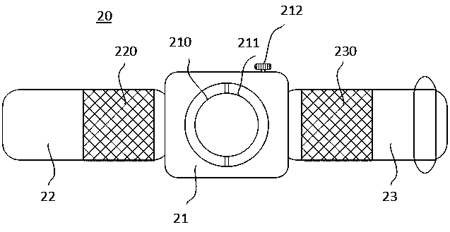
[0041] figure 2 This is a bottom view of a wearable electronic device provided by the first embodiment of this application. Such as figure 2 As shown, the wearable electronic device 20 includes a body 21, a first connecting strap 22 and a second connecting strap 23. The first connecting strap 22 and the second connecting strap 23 are respectively connected to both sides of the body 21; the body 21 includes The first contact end 210 and the second contact end 211 at the bottom; the first connection strip 22 includes a third contact end 220 disposed thereon, the third contact end 220 and the first contact end 210 are electrically connected to form a first electrode , The first electrode is used to contact the object under test; the second connecting strip 23 includes a fourth contact end 230 disposed thereon, the fourth contact end 230 and the second contact end 211 are electrically connected to form a second electrode, The second electrode is used to contact the object under test; the wearable electronic device further includes a third electrode 212; the wearable electronic device passes through the first electrode, the second electrode, and the third electrode 212 Acquire ECG information of the measured object.
[0042] Exemplarily, the wearable electronic device 20 is a smart bracelet, which is worn on the wrist of the subject.
[0043] Exemplarily, the first contact end 210 and the second contact end 211 may be metal sheets.
[0044] Exemplarily, the third contact end 220 and the fourth contact end 230 may be flexible conductive objects, or metal wire mesh objects, such as metal conductive cloth, or conductive objects formed of flexible thin-film conductive materials.
[0045] Exemplarily, the third electrode 212 is a metal key provided on the side of the main body 21.
[0046] In the embodiment of the present application, the first electrode and the second electrode are extended from the bottom of the body to the connecting strap, and the first electrode includes a first contact end arranged on the bottom of the body and a third contact end arranged on the first connecting strap. , The second electrode includes a second contact end arranged on the bottom of the body and a fourth contact end arranged on the second connecting strip, thereby increasing the area of the first electrode and the second electrode, so that the first electrode and the second electrode Good contact with the skin of the tested object. The first electrode has good contact with the skin of the measured object, which reduces the contact impedance formed by the first electrode and the skin of the measured object, increases the amplitude of the ECG signal collected by the first electrode and reduces noise Interference, the accuracy of the ECG signal collected by the first electrode is an order of magnitude higher than the ECG signal detected by the existing wearable electronic device, thereby improving the detection accuracy; and the first electrode is arranged at the bottom of the body The ECG signals collected by the contact terminal and the contact terminal provided on the connection belt can compensate each other, so that the first electrode can stably collect high-quality ECG signals, even when the wearable electronic device and the measured object In the case of poor skin contact, even in the state of exercise, the first electrode can still collect high-quality ECG signals stably, thereby improving the detection stability of the wearable electronic device. The second electrode is in good contact with the skin of the object under test, so that the second electrode can feed back the common mode signal to the detection circuit to eliminate common mode interference in the detection circuit, thereby improving detection accuracy.
[0047] As a preferred embodiment, the areas of the first contact end 210 and the second contact end 211 are equal.
[0048] As a preferred embodiment, the areas of the third contact end 220 and the fourth contact end 230 are equal.
[0049] When the areas of the first contact end 210 and the second contact end 211 are equal, and the areas of the third contact end 220 and the fourth contact end 230 are equal, the first electrode and the second electrode are in good contact with the skin of the measured object , Thereby improving the detection accuracy; in addition, when the area of the first electrode and the second electrode are equal, the arrangement of the first electrode and the second electrode in appearance is more beautiful.
[0050] As a preferred embodiment, the first contact end 210 and the second contact end 211 are symmetrically distributed with respect to the central axis of the bottom of the body 21.
[0051] As a preferred embodiment, the third contact end 220 and the fourth contact end 230 are symmetrically distributed with respect to the central axis of the bottom of the body 21.
[0052] When the first contact end 210 and the second contact end 211 are symmetrically distributed about the central axis of the bottom of the body 21, and the third contact end 220 and the fourth contact end 230 are symmetrically distributed about the central axis of the bottom of the body 21, the first electrode The arrangement of the second electrode and the second electrode is more beautiful, and the first electrode and the second electrode are in good contact with the skin of the tested object, thereby improving the detection accuracy.
[0053] As a preferred embodiment, the first connecting strap 22 and the second connecting strap 23 may be flexible connecting straps. For example, the flexible connecting strap may be a connection made of a thermoplastic elastomer (Thermo-plastic Elastomer, TPE) material. band.
[0054] As a preferred embodiment, the third contact end 220 and the fourth contact end 230 respectively provided on the first connecting strip 22 and the second connecting strip 23 are both flexible conductive materials, for example, the third contact The terminal 220 and the fourth contact terminal 230 may be metal conductive cloth or a conductive flexible film.
[0055] When the first connection belt 22, the second connection belt 23, and the third contact end 220 and the fourth contact end 230 respectively provided on the first connection belt 22 and the second connection belt 23 are all flexible materials, the third contact The terminal 220 and the fourth contact terminal 230 have a good wearing fit with the skin of the tested object. At this time, the first electrode and the second electrode are in good contact with the skin of the tested object. Accordingly, the wearable electronic device 20 can Obtain high-quality ECG signals and eliminate common-mode interference in the circuit, thereby improving the accuracy of ECG detection.
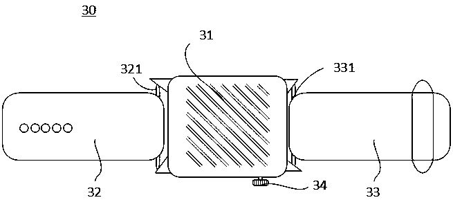
[0056] Figure 3a~Figure 3c They are respectively a top view, a bottom view, and a cross-sectional view of a wearable electronic device provided by another embodiment of the present application. The wearable electronic device 30 includes a body 31, a first connecting strap 32 and a second connecting strap 33. The body 31 includes a first contact end 310, a second contact end 311, a first connection part 312, a second connection part 313, a PCB circuit board 314 and a battery 315; the first contact end 310 and the second contact end 311 have the same shape, The first contact end 310 and the second contact end 311 are arranged at the bottom of the body 31 and are distributed symmetrically with respect to the central axis of the bottom of the body 31; specifically, the first contact end 310 and the second contact end 311 are arranged on the body 31 Two semicircular ring electrodes at the bottom and symmetrically distributed with respect to the central axis of the bottom of the main body 31;
[0057] The first contact end 310 is in electrical contact with the first connection portion 312, the second contact end 311 is in electrical contact with the second connection portion 313, and both the first connection portion 312 and the second connection portion 313 are in electrical contact with the PCB circuit board 314, so The first contact end 310 and the second contact end 311 are in electrical communication with the PCB circuit board 314, and the PCB circuit board 314 is used to calculate and obtain the electrocardiographic information of the measured object according to the collected electrocardiographic signals. Specifically, the first contact end 310 and the second contact end 311 may be metal sheets or transparent conductive objects, and the first connection portion 312 and the second connection portion 313 may be metal elastic sheets or conductive foam.
[0058] The first connecting strap 32 includes a third contact end 320 and a first green ear 321. The first ear 321 penetrates through one end of the first connecting strap 32 and is used to connect the first connecting strap 32 and the body 31; the third contact end 320 is arranged on the first connecting strap 32; the third contact end 320 is connected to the first connecting strap 32. The whole ear 321 is electrically connected, and the first connecting portion 312 is electrically connected to the first ear 321. Therefore, the third contact end 320 and the first contact end 310 are electrically connected to form a first electrode; the second connection strip 33 includes a fourth contact The end 330 and the second lug 331, the second lug 331 penetrates through one end of the second connecting strap 33, and is used to connect the second connecting strap 33 and the body 31; the fourth contact end 330 is arranged on the second connecting strap 33 The fourth contact end 330 is electrically connected to the second green ear 331, and the second connection portion 313 is electrically connected to the second green ear 331, so the fourth contact end 330 and the second contact end 311 are electrically connected to form a second electrode.
[0059] Specifically, the first lug 321 and the second lug 331 may be metal pins, and the third contact end 320 and the fourth contact end 330 may be flexible conductive objects with the same shape, such as metal conductive cloth or conductive flexible The third contact end 320 is connected to the first green ear 321 by a wire, the first connection portion 312 is connected to the first green ear 321 by a wire, and the first contact end 310 and the first connection portion 312 are in electrical contact, so The third contact end 320 and the first contact end 310 are electrically connected to form a first electrode; the fourth contact end 330 is connected to the second green ear 331 by a metal wire, and the second connection portion 313 is connected to the second green ear 331 by a metal wire , And the second contact end 320 and the second connection portion 313 are in electrical contact, so the fourth contact end 330 and the second contact end 311 are electrically connected to form a second electrode; the third contact end 320 and the fourth contact end 330 have the same shape , And the third contact end 320 and the fourth contact end 330 are symmetrically distributed about the central axis of the bottom of the body 31.
[0060] The main body 31 also includes a third electrode 34 arranged on one side of the main body 31, specifically, the third electrode 34 is a metal button on the side of the main body.
[0061] In practical applications, the wearable electronic device 30 can be worn on the wrist of the subject, and the first electrode and the second electrode are in contact with the skin of the wrist. When the measured object actively touches the third electrode 34, the first electrode and the third electrode 34 respectively collect the ECG signals of different parts of the measured object, and the second electrode is based on the data collected by the first electrode and the third electrode 34. The ECG signal is summed to obtain the size of the common mode signal, and the common mode signal is fed back to the detection circuit to eliminate common mode interference in the detection circuit. The PCB circuit board 314 calculates the measured object according to the collected ECG signal ECG information.
[0062] In the embodiment of the present application, by extending the first electrode and the second electrode from the bottom of the body to the connected belt, the area of the first electrode and the second electrode is increased, so that the first electrode and the second electrode are The skin of the subject is in good contact, increasing the amplitude of the ECG signal collected by the first electrode and reducing noise interference, and the second electrode can feed back the size of the common mode signal to the detection circuit, thereby eliminating the common mode in the detection circuit Signal interference improves the accuracy of ECG detection; and the first electrode and the second electrode are symmetrically distributed with respect to the central axis of the bottom of the body, making the first electrode and the second electrode easier to implement in the process, and the appearance is more beautiful In addition, the ECG signals collected by the contact end of the first electrode at the bottom of the body and the contact end of the connection belt can compensate each other, so the first electrode can stably collect high-quality ECG signals, even in poor contact The same is true for the situation, so the wearable electronic device provided by the embodiments of the present application has good detection stability and high detection accuracy.
[0063] Figure 4a~Figure 4c They are respectively a top view, a bottom view, and a cross-sectional view of a wearable electronic device provided by another embodiment of the present application. The wearable electronic device 40 includes a body 41, a first connection band 42 and a second connection band 43. The body 41 includes a first contact end 410, a second contact end 411, a first connection part 412, a second connection part 413, a PCB circuit board 414, a first male end 415 and a second male end 416; the first contact end 410 and The shape of the second contact end 411 is the same. The first contact end 410 and the second contact end 411 are arranged at the bottom of the main body 41 and are distributed symmetrically with respect to the central axis of the bottom of the main body 41; specifically, the first contact end 410 and the second contact end 410 The contact ends 411 are two semicircular ring electrodes arranged at the bottom of the body 41 and symmetrically distributed with respect to the central axis of the bottom of the body 41;
[0064] The first contact end 410 is in electrical contact with the first connection portion 412, the second contact end 411 is in electrical contact with the second connection portion 413, and both the first and second connection portions 412 and 413 are in electrical contact with the PCB circuit board 414, therefore The first contact end 4140 and the second contact end 411 are in electrical communication with the PCB circuit board 414, and the PCB circuit board 414 is used to calculate and obtain the ECG information of the measured object according to the collected ECG signal. Specifically, the first contact end 410 and the second contact end 411 may be metal sheets or transparent conductive objects, and the first connection portion 412 and the second connection portion 413 may be metal elastic sheets or conductive foam.
[0065] The first male end 415 and the second male end 416 are symmetrically arranged on both sides of the main body 41. Specifically, the first male end 415 includes a first protrusion, and a first metal contact is provided on the first protrusion. The two male ends 416 include a second protrusion, and a third metal contact is provided on the second protrusion.
[0066] The first connecting strap 42 includes a third contact end 420 and a first female end 421. The first female end 421 is provided at one end of the first connecting strap 42, the first female end 421 includes a first recessed portion, the first recessed portion is provided with a second metal contact, the first female end 421 and the first male end 415 The third contact end 420 is arranged on the first connecting belt 42; the third contact end 420 is electrically connected to the second metal contact, and the first connecting portion 412 and the first male end 415 are electrically connected. A metal contact is electrically connected, so the third contact end 420 and the first contact end 410 are electrically connected to form a first electrode; the second connection strap 43 includes a fourth contact end 430 and a second female end 431. The second female end 431 is provided at one end of the second connecting strap 43, the second female end 431 includes a second recessed portion, the second recessed portion is provided with a fourth metal contact, the second female end 431 and the second male end 416 The fourth contact end 430 is arranged on the second connection belt 43; the fourth contact end 430 is electrically connected to the fourth metal contact, and the second connection portion 413 and the second male end 416 are electrically connected. The three metal contacts are electrically connected, so the fourth contact end 430 and the second contact end 411 are electrically connected to form a second electrode.
[0067] Specifically, the third contact end 420 and the fourth contact end 430 can be flexible conductive objects with the same shape, such as a metal conductive cloth or a conductive flexible film; the third contact end 420 is connected to the first female end by a metal wire 421, the first connecting portion 412 is connected to the first metal contact on the first male end 415 by a wire, and the first contact end 410 is in electrical contact with the first connecting portion 412, so the third contact The terminal 420 and the first contact terminal 410 are electrically connected to form a first electrode; the fourth contact terminal 430 is connected to the fourth metal contact of the second female terminal 431 through a metal wire, and the second connecting portion 413 is connected to the second terminal through a metal wire. The third metal contact on the male end 416, and the second contact end 411 is in electrical contact with the second connection portion 413, so the fourth contact end 430 and the second contact end 411 are electrically connected to form a second electrode; the third contact end 420 and the fourth contact end 430 have the same shape, and the third contact end 420 and the fourth contact end 430 are symmetrically distributed with respect to the central axis of the bottom of the body 41.
[0068] The main body 41 also includes a third electrode 44 arranged on one side of the main body. Specifically, the third electrode 44 is a metal button on the side of the main body.
[0069] In practical applications, the wearable electronic device can be worn on the wrist of the subject, and the first electrode and the second electrode are in contact with the skin on the wrist. When the measured object actively touches the third electrode 44, the first electrode and the third electrode 44 respectively collect the ECG signals of different parts of the measured object, and the second electrode is based on the data collected by the first electrode and the third electrode 44. The ECG signal is summed to obtain the size of the common mode signal, and the common mode signal is fed back to the detection circuit to eliminate common mode interference in the detection circuit. The PCB circuit board 414 calculates the measured object according to the collected ECG signal ECG information.
[0070] In the embodiment of the present application, by extending the first electrode and the second electrode from the bottom of the body to the connected belt, the area of the first electrode and the second electrode is increased, so that the first electrode and the second electrode are The skin of the subject is in good contact, increasing the amplitude of the ECG signal collected by the first electrode and reducing noise interference, and the second electrode can feed back the size of the common mode signal to the detection circuit, thereby eliminating the common mode in the detection circuit Signal interference improves the accuracy of ECG detection; and the first electrode and the second electrode are symmetrically distributed with respect to the central axis of the bottom of the body, making the first electrode and the second electrode easier to implement in the process, and the appearance is more beautiful In addition, the ECG signals collected by the contact end of the first electrode at the bottom of the body and the contact end of the connection belt can compensate each other, so the first electrode can stably collect high-quality ECG signals, even in poor contact The same is true for the situation, so the wearable electronic device provided by the embodiments of the present application has good detection stability and high detection accuracy.
[0071] In the embodiment of the present application, a first male end 415 and a second male end 416 are provided at the bottom of the body, and a first female end 421 and a second female end 431 are respectively provided on the first connecting belt and the second connecting belt, thereby realizing the first A contact end 410 and a third contact end 420 are electrically connected to form a first electrode, and the second contact end 411 and a fourth contact end 430 are electrically connected to form a second electrode. This solution is easy to implement in terms of process.
[0072] As a preferred embodiment, on the plane where the first metal contact is located, the gap between the first metal contact and the first male end 415 is filled with waterproof insulating material; On the plane, the gap between the second metal contact and the first female end 421 is filled with waterproof insulating material; on the plane where the third metal contact is located, the gap between the third metal contact and the second male end 416 The gap is filled with waterproof insulating material; on the plane where the fourth metal contact is located, the gap between the fourth metal contact and the second female terminal 431 is filled with waterproof insulating material, so as to achieve a waterproof effect.
[0073] Optionally, the waterproof insulating material may be transparent UV glue.
[0074] When the first male end 415, the second male end 416, the first female end 421 or the second female end 431 cannot be completely matched with their corresponding metal contacts, that is, the first male end 415, the second male end 416, and the When there is a gap between the one female terminal 421 or the second female terminal 431 and the corresponding metal contact, then liquid such as sweat can enter the wearable electronic device through the gap, causing an internal short circuit of the wearable electronic device. Therefore, filling the gap with a waterproof and non-conductive material can effectively prevent liquid from entering the wearable electronic device, thereby preventing the phenomenon of internal short circuit caused by it.
[0075] It should be noted that, under the premise of no conflict, the various embodiments described in this application and/or the technical features in each embodiment can be combined with each other arbitrarily, and the technical solutions obtained after the combination should also fall within the protection scope of this application. .
[0076] It should be understood that the specific examples in the embodiments of the present application are only to help those skilled in the art to better understand the embodiments of the present application, rather than limiting the scope of the embodiments of the present application. Those skilled in the art can base on the above-mentioned embodiments. Various improvements and modifications are made, and these improvements or modifications fall within the scope of protection of the present application.
[0077] The above are only specific implementations of this application, but the protection scope of this application is not limited to this. Any person skilled in the art can easily think of changes or substitutions within the technical scope disclosed in this application. Should be covered within the scope of protection of this application. Therefore, the protection scope of this application should be subject to the protection scope of the claims.
PUM


Description & Claims & Application Information
We can also present the details of the Description, Claims and Application information to help users get a comprehensive understanding of the technical details of the patent, such as background art, summary of invention, brief description of drawings, description of embodiments, and other original content. On the other hand, users can also determine the specific scope of protection of the technology through the list of claims; as well as understand the changes in the life cycle of the technology with the presentation of the patent timeline. Login to view more.
Similar technology patents
Array substrate and display device
Owner:HEFEI XINSHENG OPTOELECTRONICS TECH CO LTD +1
Bracket for industrial machine tools
Owner:郭能超
Chain capable of reducing weight
Owner:超汇桂盟传动(苏州)有限公司
Papermaking waste liquid treating device
Owner:HUBEI HUAHAI FIBER TECH
Classification and recommendation of technical efficacy words
- increase the area
- Reduce contact resistance
Array substrate, fabricating method for same and liquid crystal display panel
Owner:SHANGHAI TIANMA MICRO ELECTRONICS CO LTD
Ultra-junction longitudinal bilateral diffusion metal oxide semiconductor tube
Owner:SOUTHEAST UNIV
Input equipment and computer comprising same
Owner:LENOVO (BEIJING) CO LTD
Nitride semiconductor device and method for manufacturing same
Owner:PANASONIC CORP
Broadband high-gain circularly polarized microstrip antenna
Owner:BEIJING RES INST OF TELEMETRY +1
Semiconductor device and method for manufacturing the same
Owner:SONY CORP
Organic light emitting display device and manufacturing method thereof
Owner:KUNSHAN GO VISIONOX OPTO ELECTRONICS CO LTD
Organic thin film transistor and flat panel display comprising the same
Owner:SAMSUNG DISPLAY CO LTD
Surface treatment method of metal oxide and preparation method of thin film transistor
Owner:BOE TECH GRP CO LTD