Gas inlet cleaning device and waste gas treatment device adopting same

A waste gas treatment device and cleaning device technology, which is applied in the direction of gas treatment, cleaning methods and appliances, smoke and dust removal, etc., can solve the problems of unsatisfactory demand and low waste gas treatment efficiency, and achieve cost saving, maintenance time reduction, and avoiding stuck Effect

Active Publication Date: 2020-07-17
YANGTZE MEMORY TECH CO LTD
View PDF7 Cites 1 Cited by
  • Summary
  • Abstract
  • Description
  • Claims
  • Application Information

AI Technical Summary

Problems solved by technology

[0003] However, the exhaust gas treatment efficiency of the existing exhaust gas treatment devices is low and cannot meet the demand

Method used


Image

  • Gas inlet cleaning device and waste gas treatment device adopting same
  • Gas inlet cleaning device and waste gas treatment device adopting same
  • Gas inlet cleaning device and waste gas treatment device adopting same

Examples


Embodiment Construction

[0024] The specific implementations of the air inlet cleaning device provided by the present invention and the exhaust gas treatment device using the cleaning device will be described in detail below with reference to the accompanying drawings.

[0025] Industrial waste gas usually contains particulate matter. At the air inlet of the exhaust gas treatment device, particulate matter may accumulate and block the air inlet. Generally, an intake port cleaning device is provided at the intake port of the exhaust gas treatment device to prevent exhaust gas from accumulating at the intake port while introducing exhaust gas.

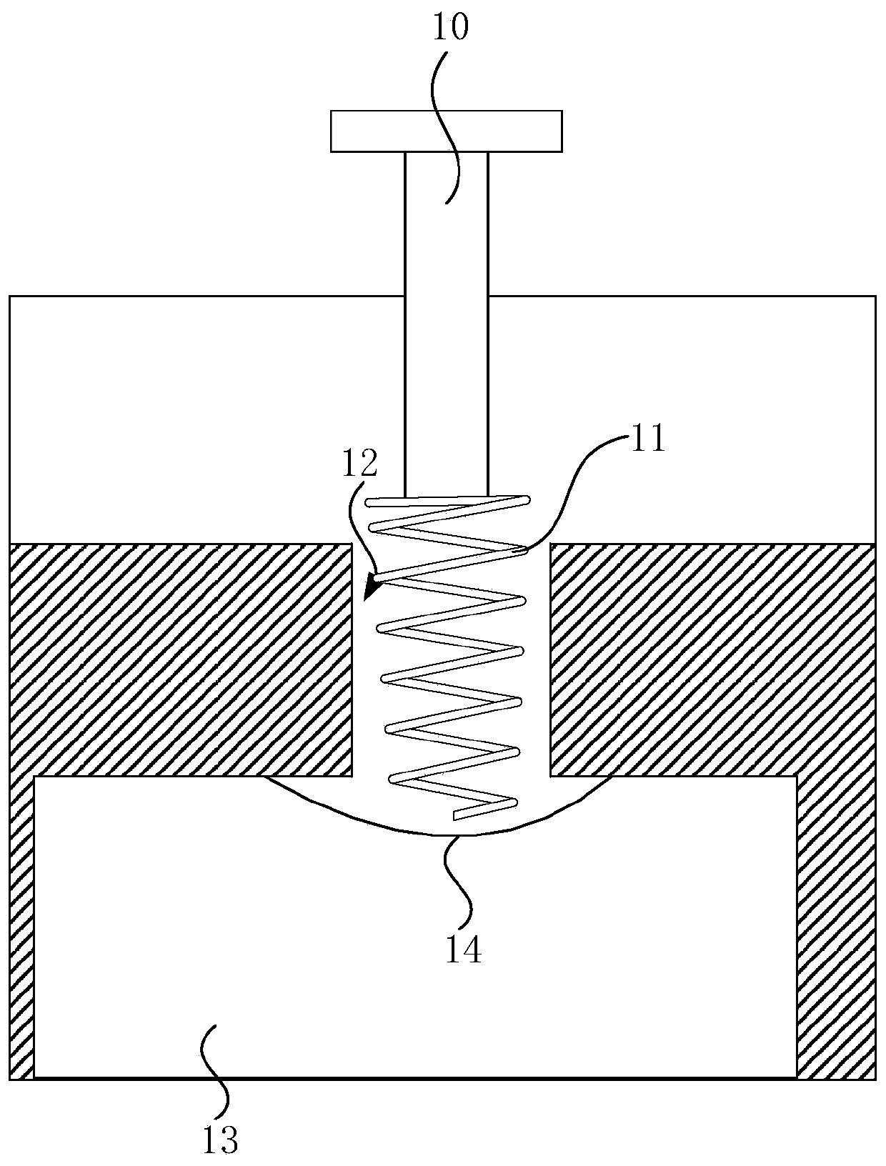
[0026] figure 1 It is a schematic diagram of an existing exhaust gas treatment device. See figure 1 The exhaust gas treatment device drives the cleaning member 11 to move in the air inlet 12 through a sliding rod 10 to clean the air inlet. Specifically, during the intake period, the cleaning member 11 moves to drive the particulate matter in the exhaust gas to move,...


PUM


Abstract

The invention provides a gas inlet cleaning device and a waste gas treatment device adopting the same; the gas inlet cleaning device comprises: a cylinder body having a containing cavity; the slidingrod that comprises a first end and a second end which are oppositely arranged, the first end penetrates through the end of the cylinder body and extends into the containing cavity, and the second endis located outside the containing cavity; the protective sleeve that is arranged outside the cylinder body and arranged on the sliding rod in a sleeving mode, the protective sleeve comprises a fixed end and a movable end which are oppositely arranged, the fixed end abuts against the end of the cylinder body, the movable end is connected with the second end of the sliding rod, and the protective sleeve is of a telescopic structure; the cleaning piece that is connected with the second end of the sliding rod; in the extending direction of the sliding rod, the sliding rod can slide relative to thecontaining cavity, and then the cleaning piece is driven to move so as to clean the gas inlet. The gas inlet cleaning device has the advantages that the sliding rod is isolated from the external environment, so that the sliding of the sliding rod is prevented from being influenced by external high temperature and particulate matters, and the loss of the gas inlet cleaning device is reduced.

Description

Technical field [0001] The present invention relates to the field of exhaust gas treatment, in particular to an air inlet cleaning device and an exhaust gas treatment device adopting the cleaning device. Background technique [0002] In the current semiconductor manufacturing process, toxic industrial waste gas is generated. These industrial waste gas needs to be treated before it can be discharged into the atmosphere, otherwise it will cause pollution and pollution to the environment. People are paying more and more attention to environmental protection. How to properly handle industrial waste gas and avoid its environmental pollution has become a vital part of industrial production. [0003] However, the exhaust gas treatment efficiency of the existing exhaust gas treatment device is low and cannot meet the demand. Summary of the invention [0004] The technical problem to be solved by the present invention is to provide an air inlet cleaning device and an exhaust gas treatment d...

Claims


Application Information

Patent Timeline
Patent Type & Authority Applications(China)
IPC IPC(8): B01D49/00B01D53/00B08B15/04B08B1/00F23G7/06
CPCB01D49/00B01D53/00B08B15/04B08B1/00F23G7/06B01D2258/0216
Inventor 王伟
Owner YANGTZE MEMORY TECH CO LTD
Why Eureka
Try Eureka