Dry-type mixing tank

A mixing tank and dry-type technology, applied in mixers, mixers with rotating stirring devices, dissolving, etc., can solve the problems of increasing difficulty and affecting the efficiency of stirring, so as to reduce the time of stirring, ensure the effect, and ensure efficiency effect

Inactive Publication Date: 2020-07-17
马慧慧
View PDF0 Cites 2 Cited by
  • Summary
  • Abstract
  • Description
  • Claims
  • Application Information

AI Technical Summary

Problems solved by technology

[0003] Since most of the existing mixing tanks first put all the materials into the tank body, and then realize the mixing of the materials through the stirring of the stirring blades, if more materials are put in at the first time, it will not only increase the difficulty of mixing , and the efficiency of stirring is greatly affected, in view of this, the present invention provides a dry mixing tank, which can change the way of feeding materials, so that the difficulty and efficiency of stirring can be improved and optimized

Method used


Image

  • Dry-type mixing tank
  • Dry-type mixing tank
  • Dry-type mixing tank

Examples


Embodiment Construction

[0020] In order to make the technical means, creative features, goals and effects achieved by the present invention easy to understand, the present invention will be further described below in conjunction with specific embodiments.

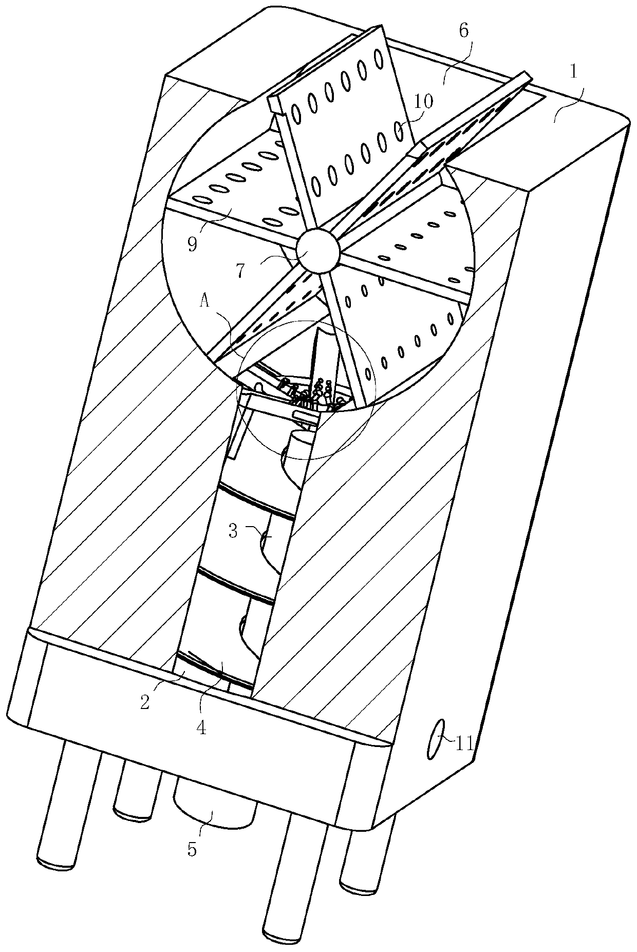
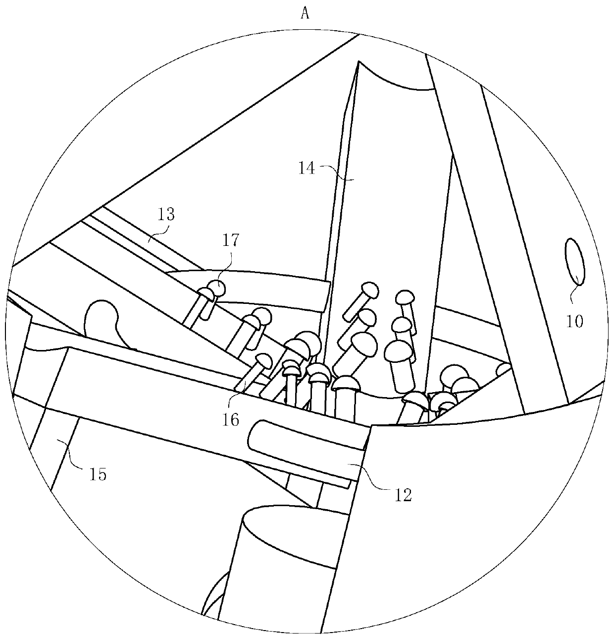
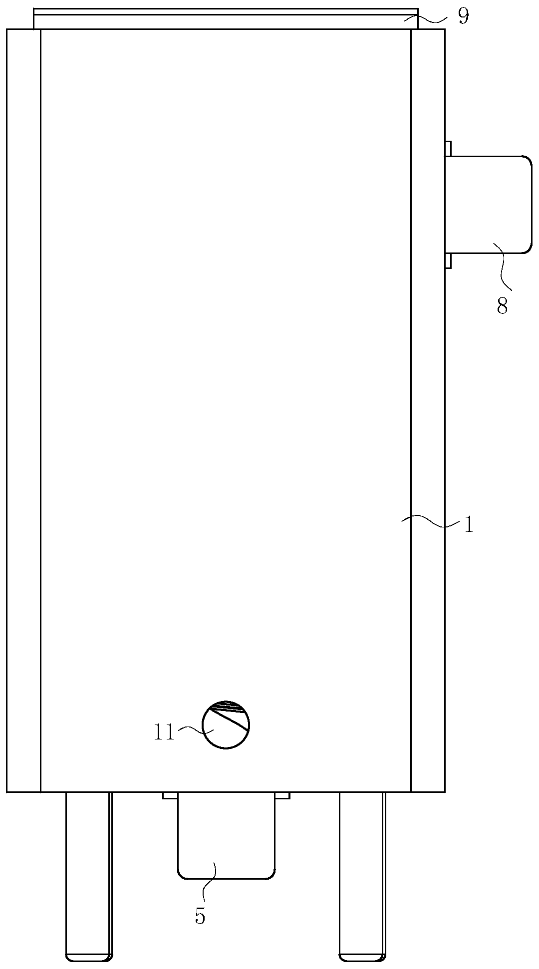
[0021] Such as Figure 1-4As shown, a dry mixing tank according to the present invention includes a tank body 1, a main mixing chamber 2 is opened downward along the middle of the tank body 1, and a main rotating shaft is arranged inside the main mixing chamber 2 3. The surface of the main rotating shaft 3 is provided with a spiral blade 4, the bottom of the main rotating shaft 3 is connected to the main motor 5, and the main motor 5 is installed at the bottom of the tank body 1; the top of the main mixing chamber 2 is provided with a secondary mixing chamber along the horizontal direction. chamber 6, and the bottom of the auxiliary mixing chamber 6 communicates with the main mixing chamber 2, and the top of the auxiliary mixing chamber 6 is open,...


PUM


Abstract

The invention belongs to the technical field of mixing equipment, and particularly relates to a dry-type mixing tank which comprises a tank body, a main mixing chamber is downwards formed in the tankbody along the middle part, a main rotating shaft is arranged in the main mixing chamber, spiral blades are arranged on the surface of the main rotating shaft, the bottom of the main rotating shaft isconnected with a main motor, and the main motor is mounted at the bottom of the tank body; an auxiliary mixing chamber is arranged at the top of the main mixing chamber; in the rotating process of the auxiliary motor, when shifting plates rotate, the dry materials between the two adjacent shifting plates are enable to enter the space between other two shifting plates through the leakage holes; initial mixing on the dry materials is carried out; meanwhile, when the shifting plates rotate to the bottom of the auxiliary mixing chamber, one part of the dry materials are enable to enter the mainmixing chamber from the position where the bottom of the auxiliary mixing chamber is communicated with the main mixing chamber, and due to the fact that the dry materials are initially mixed, when thespiral blades are used for stirring, the stirring time is greatly shortened, and then the stirring efficiency is improved.

Description

technical field [0001] The invention belongs to the technical field of mixing equipment, in particular to a dry mixing tank. Background technique [0002] The mixing tank can also be called the water phase tank, which is widely used in coatings, medicine, building materials, chemicals, pigments, resins, food, scientific research and other industries. The equipment can be made of carbon steel, stainless steel and other materials according to the process requirements of the user's products, and can be equipped with heating and cooling devices to meet different process and production needs. Heating forms include jacket electric heating and coil heating. The equipment has reasonable structure design, advanced technology, durability, simple operation and convenient use. It is an ideal chemical equipment with less investment, quick commissioning and high income. Among them , A mixing tank that adds water for mixing is called a wet mixing tank, while a mixing tank that only mixes ...

Claims


Application Information

Patent Timeline
IPC IPC(8): B01F13/10B01F15/00B01F7/00
CPCB01F27/1921B01F33/811B01F35/3204
Inventor 马慧慧
Owner 马慧慧
Why Eureka
Try Eureka