A support device for grinding thin-walled parts

A technology for supporting devices and thin-walled parts, which is used in positioning devices, grinding workpiece supports, metal processing machinery parts, etc., which can solve the problem of poor tooling versatility, limiting the workable area of ​​parts, and inability to realize the inner steps of thin-walled rotary parts. Hole processing and other problems, to achieve the effect of high processing accuracy, ensuring stability, and expanding the machinable area

Active Publication Date: 2022-03-22
JINHUA DAZHONG GEAR
View PDF8 Cites 0 Cited by
  • Summary
  • Abstract
  • Description
  • Claims
  • Application Information

AI Technical Summary

Problems solved by technology

[0003] However, there are the following problems in the use of tooling such as internally expanding mandrels used for turning the outer circle and end face of thin-walled rotary parts: First, the size of each internally expanding mandrel tooling is the same as that of thin-walled rotary parts The size of the inner hole is the matching size. Due to the inconsistency of the inner hole size of the parts in different processing stages, it is necessary to customize a new inner expansion mandrel tooling to achieve size matching and clamping. The versatility of the tooling is poor; the second is to obtain enough The clamping force of the thin-walled rotary part is set outside the inner expansion mandrel when in use, and the mandrel protrudes from both ends of the part, so it is impossible to process the inner step and inner hole of the thin-walled rotary part, and the shape of the tooling is limited. Machinable area of ​​the part

Method used


Image

  • A support device for grinding thin-walled parts
  • A support device for grinding thin-walled parts
  • A support device for grinding thin-walled parts

Examples


Embodiment Construction

[0050] The following will clearly and completely describe the technical solutions in the embodiments of the present invention with reference to the accompanying drawings in the embodiments of the present invention. Obviously, the described embodiments are only some, not all, embodiments of the present invention. Based on the embodiments of the present invention, all other embodiments obtained by persons of ordinary skill in the art without making creative efforts belong to the protection scope of the present invention.

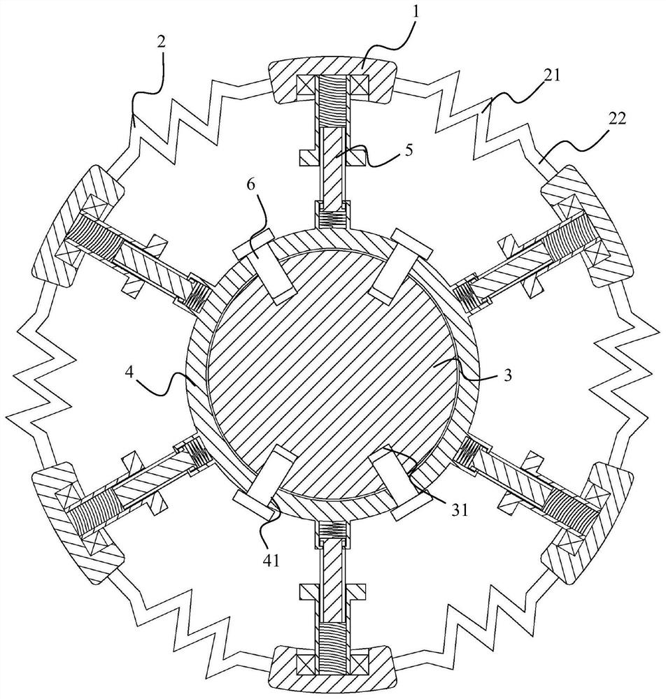
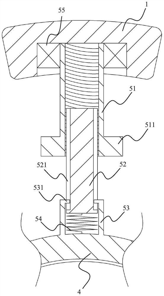
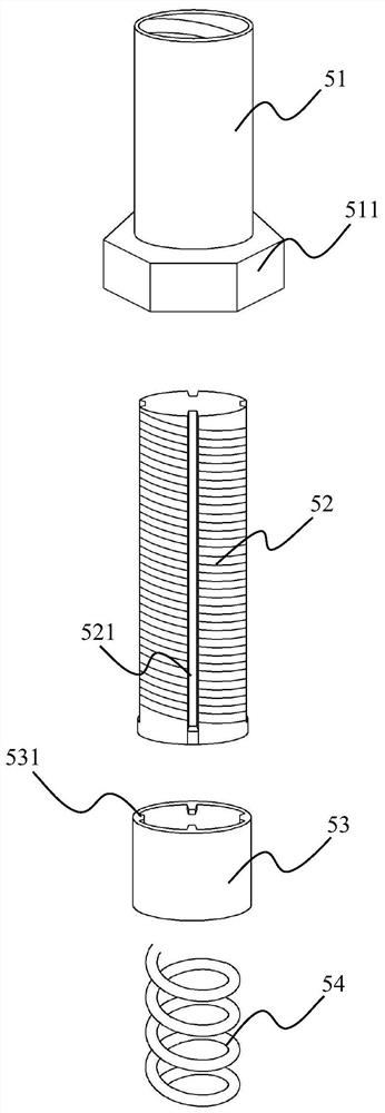
[0051] See attached figure 1 , the embodiment of the present invention discloses a support device for grinding thin-walled parts, including: a support block 1, a spring rod 2, a fixed shaft 3, a fixed ring 4 and an elastic telescopic rod 5;

[0052] The number of supporting blocks 1 is multiple, and they are evenly spaced in a circular arrangement;

[0053] The number of spring rods 2 is the same as the number of support blocks 1, and the two ends of the spri...


PUM


Abstract

The invention discloses a support device for grinding thin-walled parts, which comprises a support block, a spring rod, a fixed shaft, a fixed ring and an elastic telescopic rod; the number of support blocks is multiple, and they are arranged in a circular shape at regular intervals; the spring The number of rods is the same as the number of support blocks, and the two ends of the spring rods are fixedly connected to two adjacent support blocks, and the support blocks are connected by spring rods to form a ring; the fixed shaft is coaxially arranged in the circle formed by the support blocks and the spring rods inside the ring; at least one fixed ring is detachably sleeved on the fixed shaft; the number of elastic telescopic rods is the same as the number of support blocks, and one end is fixedly connected with the outer wall of the fixed ring, and the other end is connected with the inner wall of the support block, and can Adjust its length. The invention improves the versatility of the tooling, and also expands the machinable area of ​​the inner hole support process; at least one circular ring structure can be sleeved on the fixed shaft of the invention, which can ensure the stability of the support structure and the machining accuracy according to different situations. higher.

Description

technical field [0001] The invention relates to the technical field of processing thin-walled parts, in particular to a support device for grinding thin-walled revolving parts. Background technique [0002] A thin-walled rotary part is a rotary part with a diameter-to-wall thickness ratio of not less than 20. When turning the outer circle and the end face, it is necessary to use the inner hole as the positioning and clamping reference, and usually use tooling such as an internally expanding mandrel. Support the inner hole of the thin-walled rotary parts. This clamping method increases the contact area when the parts are clamped, controls the elastic deformation of the clamping, and can obtain sufficient clamping force. Therefore, it can obtain a wide range of applications in turning processing. application. [0003] However, there are the following problems in the use of tooling such as internally expanding mandrels used for turning the outer circle and end face of thin-wal...

Claims


Application Information

Patent Timeline
Patent Type & Authority Patents(China)
IPC IPC(8): B23P23/04B23Q3/06B24B41/06
CPCB23P23/02B23Q3/062B24B41/06
Inventor 毛剑毛西润朱春耕翁孟超吴江妙金才富
Owner JINHUA DAZHONG GEAR
Why Eureka
Try Eureka