
Automatic planishing equipment for surface of cylindrical pin and use method of automatic planishing equipment

A technology of pins and columns, which is applied in the field of automatic grinding equipment for cylindrical pins, can solve the problems of poor fixation of pins, increased labor intensity, and inability to insert them, so as to facilitate transfer and transportation, reduce fatigue strength, and improve work efficiency. Effect

Inactive Publication Date: 2020-07-17
滁州市云米工业设计有限公司
View PDF5 Cites 0 Cited by
  • Summary
  • Abstract
  • Description
  • Claims
  • Application Information

AI Technical Summary

Problems solved by technology

[0003] In the prior art, the surface flatness of the processed metal pin is not enough, and it is easy to be inserted in the process of use, causing inconvenience in use
Most of the existing pin grinding devices use sandpaper for manual grinding, which increases the labor intensity
[0004] During mechanical grinding, the pins are not fixed well, and the fixed pins are not easy to take out after grinding, and the grinding depth cannot be adjusted during the grinding process, which brings great trouble to the work of relevant personnel.

Method used


Image

  • Automatic planishing equipment for surface of cylindrical pin and use method of automatic planishing equipment
  • Automatic planishing equipment for surface of cylindrical pin and use method of automatic planishing equipment
  • Automatic planishing equipment for surface of cylindrical pin and use method of automatic planishing equipment

Examples


Embodiment Construction

[0038] The technical solutions in the embodiments of the present invention will be clearly and completely described below in conjunction with the accompanying drawings in the embodiments of the present invention. Obviously, the described embodiments are only a part of the embodiments of the present invention, rather than all the embodiments. Based on the embodiments of the present invention, all other embodiments obtained by those of ordinary skill in the art without creative work shall fall within the protection scope of the present invention.

[0039] In the description of the present invention, it should be understood that the terms "opening", "upper", "lower", "thickness", "top", "middle", "length", "inner", "around", etc. The indication of the orientation or position relationship is only for the convenience of describing the present invention and simplifying the description, rather than indicating or implying that the component or element referred to must have a specific orie...


PUM


Abstract

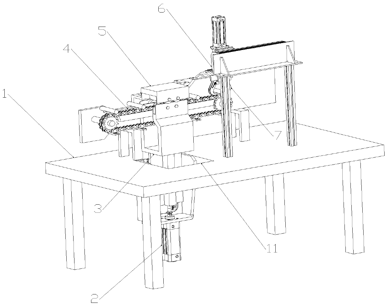
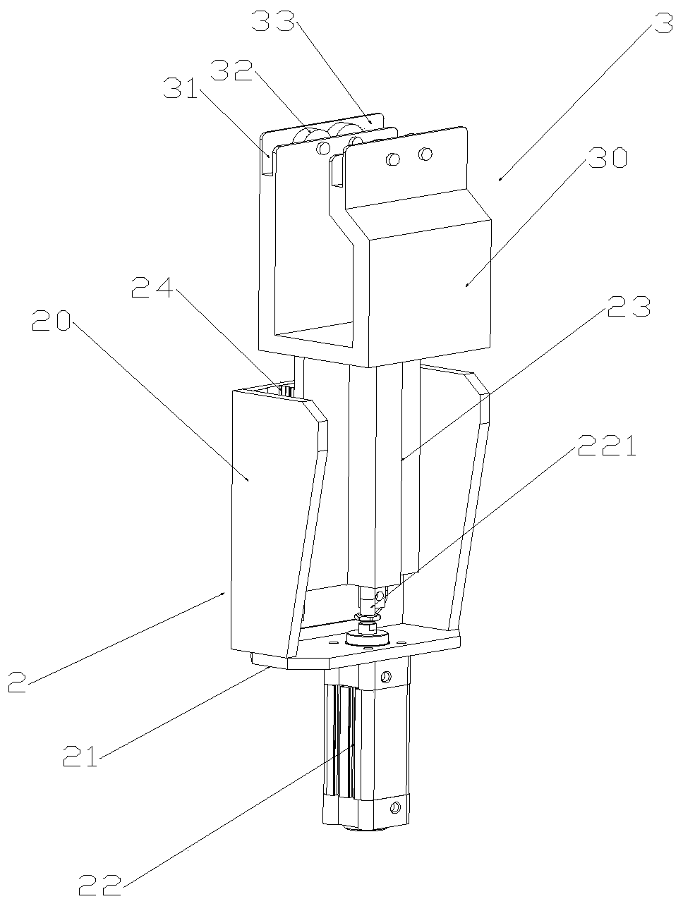
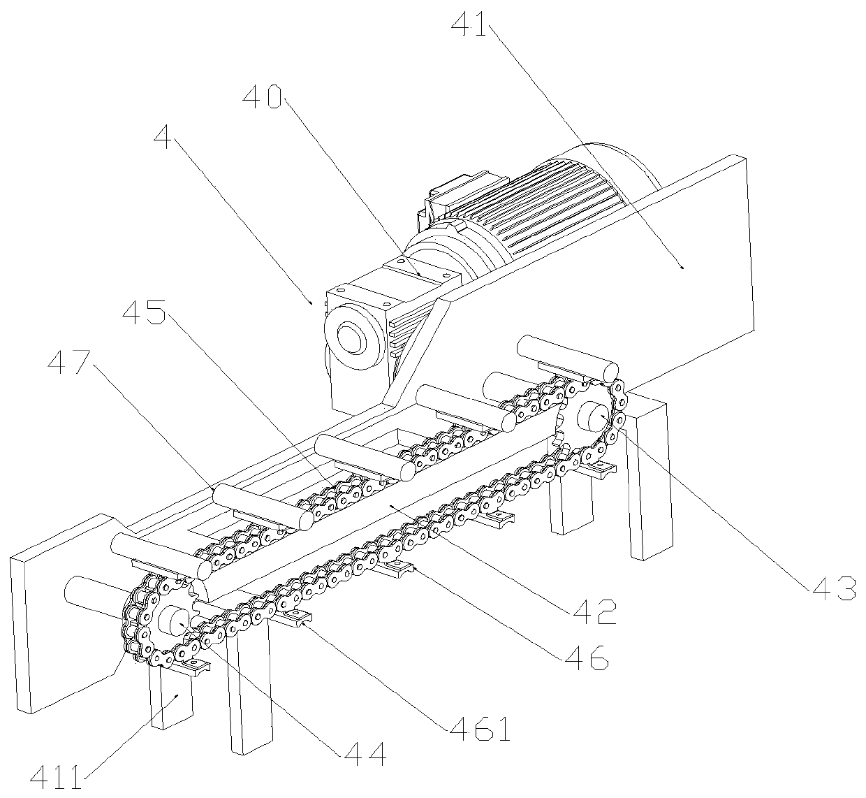
The invention discloses automatic planishing equipment for the surface of a cylindrical pin and a use method of the automatic planishing equipment. A containing mechanism and a planishing mechanism are designed; during use, a first air cylinder is driven, the containing mechanism moves upwards to jack the cylindrical pin, the cylindrical pin is arranged on two supporting wheels, the cylindrical pin continues to be jacked upwards, and the cylindrical pin and a planishing wheel are tangentially arranged; a second motor is driven, and the planishing wheel rotates to planish the cylindrical pin; in the planishing process, the height of the cylindrical pin is adjusted, and the grinding depth can be adjusted; in the work process, by means of clamping of the planishing wheel and the supporting wheels, fixing is firm, and the grinding depth can also be adjusted; meanwhile, the automatic planishing equipment is provided with a conveying mechanism; during use, it is only needed to place the cylindrical pin on a containing block, then the first motor is driven, a driving shaft rotates to drive a chain wheel to rotate, the chain wheel drives the cylindrical pin to move to the position over thecontaining mechanism, and polishing work can be completed; and the fatigue intensity of workers is reduced, and the work efficiency is improved.

Description

Technical field [0001] The invention relates to the processing field of pins, in particular to an automatic flattening equipment for the surface of a cylindrical pin and a use method thereof. Background technique [0002] Pin, namely pin. A part usually made of cylindrical wood, metal or other materials, especially used to fix several separate objects together or as a support for one object to be suspended from another object. Cylindrical pins are usually inserted in the holes to play a fixed role. [0003] In the prior art, the surface of the processed metal pin is not flat enough, and it is easy to be unable to be inserted during use, which causes inconvenience in use. Most of the existing pin polishing devices are manually polished with sandpaper, which increases labor intensity. [0004] The pins are not easy to be fixed by mechanical grinding, and the fixed pins are not easy to take out after the grinding is completed, and the grinding depth cannot be adjusted during the grin...

Claims


Application Information

Patent Timeline
IPC IPC(8): B24B5/22B24B5/307B24B5/35B24B5/50B24B41/06B24B47/12B24B47/22B24B47/00
CPCB24B5/22B24B5/307B24B5/35B24B5/355B24B5/50B24B41/06B24B47/00B24B47/12B24B47/22
Inventor 吴有军张丽丽张子武
Owner 滁州市云米工业设计有限公司
Learn More