Method and device for monitoring a brake system

a technology for brake systems and monitoring devices, applied in brake safety systems, braking systems, actuator accumulators, etc., can solve problems such as excessive expansion of belts, and achieve the effect of reducing fatigue strength and increasing material strength

Inactive Publication Date: 2005-06-09
CONTINENTAL TEVES AG & CO OHG
View PDF6 Cites 10 Cited by
  • Summary
  • Abstract
  • Description
  • Claims
  • Application Information

AI Technical Summary

Benefits of technology

[0004] In view of the above, an object of the invention is to develop a method for monitoring the media-separating element as regards its material fatigue that is due to operation. Thus, a media-separating element with an increased material strength and, thus, a reduced fatigue strength is desired to be used which is less sensitive to strong expansions and obviates the need for special protective measures regarding mechanical loads.

Problems solved by technology

The result is that it must be prevented by complicated and cost-intensive measures that the bellows will expand excessively in operation, what is considered disadvantageous.

Method used


Image

  • Method and device for monitoring a brake system
  • Method and device for monitoring a brake system

Examples


Embodiment Construction

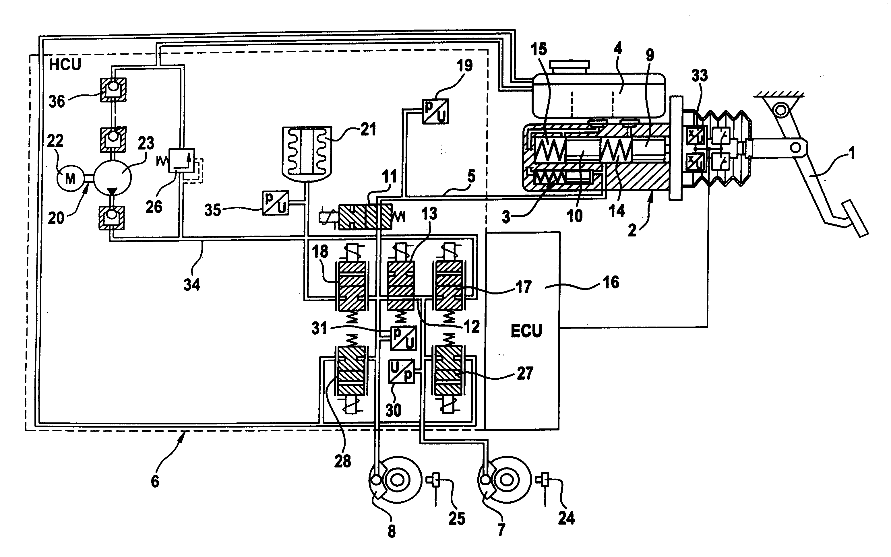
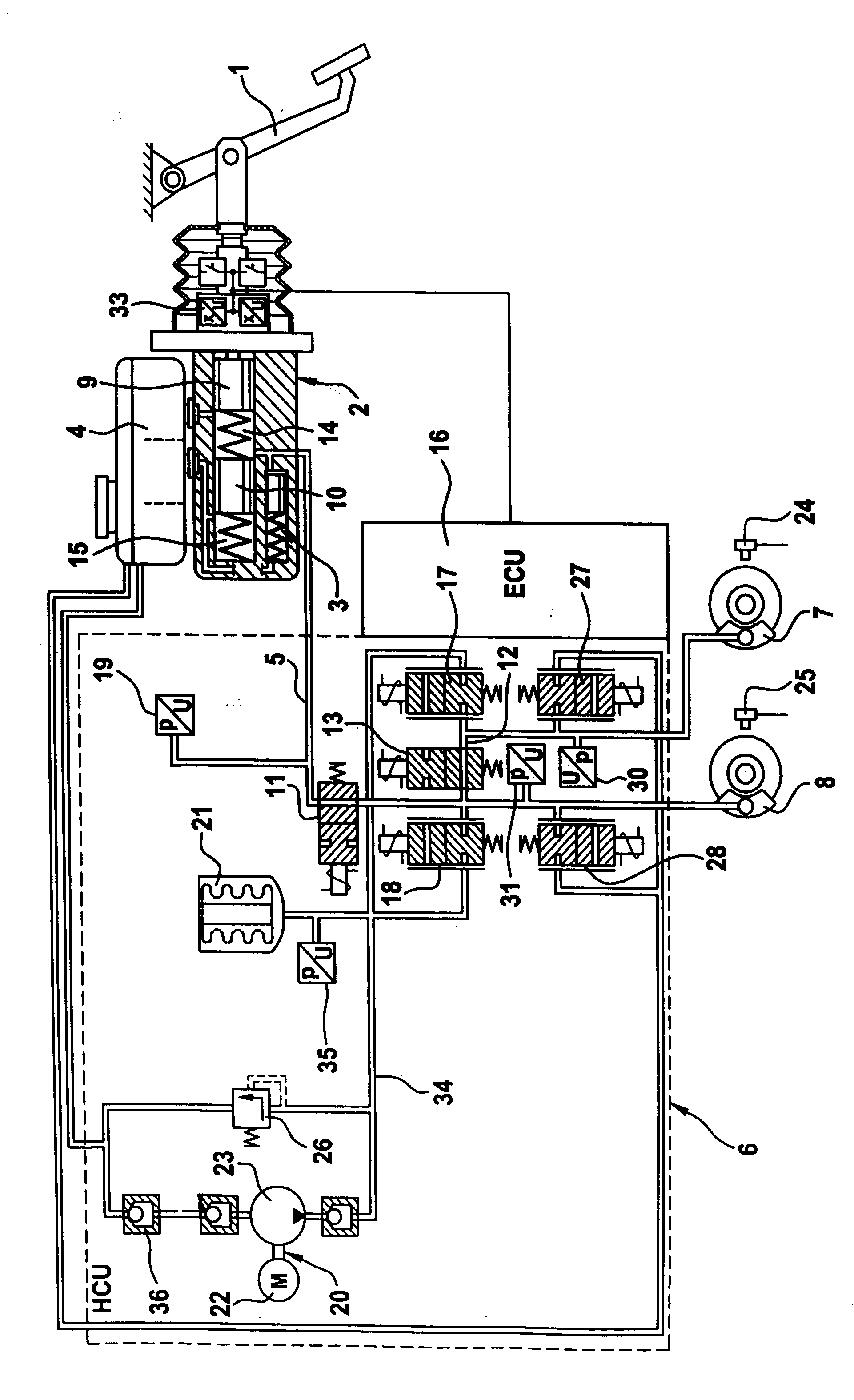
[0011] The brake system of the present invention, only represented in the drawing, is generally comprised of a dual-circuit hydraulic pressure generator or tandem-design master brake cylinder. 2 which is operable by means of a brake pedal 1, a travel simulator 3 cooperating with the tandem master cylinder 2, a pressure fluid reservoir 4 associated with the tandem master cylinder 2, a hydraulic pressure source, a control unit HCU 6 (shown only schematically) which comprises, among others, all components necessary for pressure control operations and to which wheel brakes 7, 8 associated with e.g. the rear axle of the motor vehicle are connected, as well as an electronic controlling and regulating unit 16. Wheel sensors 24, 25 (only represented) are used to determine the rotational speed of the vehicle wheels. The per se known tandem master cylinder 2 comprises pressure chambers 14, 15 separated from each other by two pistons 9, 10, said pressure chambers being connectable both to the ...


PUM


Abstract

The present invention relates to a method and a device for monitoring a brake system for motor vehicles equipped with an electronic controlling and regulating unit, as well as a hydraulic pressure accumulator that is used as an auxiliary pressure source and subdivided by a media-separating element into two chambers, the first chamber being filled with a gas and the second chamber being filled with a liquid pressure medium. To conduct a reliable monitoring of the pressure accumulator, the invention provides that the number of the partial strokes of the media-separating element is detected. To this end, brake actuations are weighted and counted according to their duration and intensity. When the sum of the weighting factors reaches a predetermined number, a warning indicates an imminent damage to the media-separating element. This renders it possible to use a less costly and less sensitive media-separating element, which obviates the need for extensive protective measures against mechanical loads.

Description

TECHNICAL FIELD [0001] The present invention generally relates to a method and a device for monitoring a brake system for motor vehicles and more particularly relates to a method and a device for monitoring a brake system for motor vehicles equipped with a hydraulic pressure accumulator. BACKGROUND OF THE INVENTION [0002] A brake system of this type is disclosed in international patent application WO 99 / 41125. An electrohydraulic brake system of the ‘brake-by-wire’ type is concerned including a means for the detection of gases disposed in the system. [0003] The pressure fluid accumulator disclosed in the international patent application WO 00 / 31420 can be used as an auxiliary pressure source in the system mentioned above. The media-separating element in this pressure accumulator is composed of a metallic bellows. To achieve a sufficient degree of fatigue strength in terms of the full extent of functioning, the bellows is made of a thin-walled material. The result is that it must be ...

Claims


Application Information

Patent Timeline
Patent Type & Authority Applications(United States)
IPC IPC(8): B60T8/17B60T8/40B60T8/88B60T17/22F15B1/08F15B19/00
CPCB60T8/409B60T17/22F15B1/08F15B19/005F15B2201/51F15B2201/31F15B2201/3153F15B2201/32F15B2201/413F15B2201/21
Inventor BUSCHMANN, GUNTHER
Owner CONTINENTAL TEVES AG & CO OHG
Why Eureka
Try Eureka