Tensioning System for a Mobile Telescopic Crane

a technology of telescopic cranes and telescopic beams, which is applied in the field of telescopic beams, can solve the problems of affecting the stability of other panel-like areas, affecting the performance of the crane, and limiting the performance capability of the telescopic beam, so as to avoid dynamic impairment, reduce weight, and improve the effect of stability

Inactive Publication Date: 2008-01-31
GROVE US LLC
View PDF4 Cites 17 Cited by
  • Summary
  • Abstract
  • Description
  • Claims
  • Application Information

AI Technical Summary

Benefits of technology

[0010] The advantage resulting from the invention is based in particular on the fact of omitting the bending beam such that the material properties of high-tensile mast materials having very high yield points can be used. Masts which are pressure-biased by tensioning means can directly absorb the pressure bias in the material and, when loaded, can use the favourable resultant tensile force. In accordance with the invention, when a system is biased in this way, the effect then arises that the bending rigidity of the jib is combined with a defined bracing force and the jib section together with the bracing and biasing forms a unit with a favourable bearing load, in all states of the crane. This creates the possibility of using masts made of high-tensile material with a low tare weight, wherein as opposed to the situation in accordance with the prior art, the high strength of the materials can also be utilised. Maximum admissible stresses in the peripheral fibres, both in the jib and in the turntable support for the counterweight and caused by bending, are compensated for by biasing and bracing.
[0015] If, as mentioned above, an inner or outer bearing point is provided is the upper portion of the mast for the tensioning means, it is advantageous to arrange said bearing point on the lowermost extending telescopic portion. This ensures that substantially the entire length of the jib can be biased.
[0019] In accordance with another embodiment variant, it is also proposed to attach the tensioning means tensile units or winches to the crane superstructure via damping units, in order to avoid dynamic impairment.
[0020] Overall, the present invention can also be defined as one in which the major components of the superstructure, for example the jib, bracing, pylons, biasing, expelling unit, turntable, counterweight and tensioning means tensile units, are designed and combined in such a way that, depending on the operational state, the individual sub-assemblies automatically perform a number of functions and mutually assist each other in a way which enables a lighter and more stable bearing design overall. The features cited in this description can be employed in this way, individually or in any combination. In particular the reduction in weight and the re-arrangement of the major components of the superstructure made possible within the framework of the invention, as well as combining them operationally, provide advantages which it has not so far been possible to achieve in the prior art.
[0021] With straight or oblique bracings comprising bracing gantries on the mast, for example, it was not possible to carry the rear and the front bracing and the cable winch while travelling on roads, because this exceeded the vehicle height and / or total admissible weight. The high assembly costs were a further disadvantage. An additional assembly crane for placing the bracing gantry was necessary and assembly work had to be performed at a height of three or four metres, at points relatively far apart, which significantly increased the risk of accidents. Cranes braced in this way contained additional weld-on structures on the jib base portion, in order to connect the bracing gantry (pylon), the erecting cylinder and the rear bracing. All these auxiliary weights increased the axle loads while travelling on roads. During operation, all the weights with respect to the bracing were situated in front of the turning centre. The weights of the bracing unit negatively effect all the bearing loads limited by the ball turning connection, the level luffing cylinder, the support presses, the chassis and the steadiness. In order to equalise the auxiliary moment from the bracing weights, a larger counterweight was necessary, resulting in extra costs for the counterweight and the turntable and chassis design, as well as additional transport costs.

Problems solved by technology

The modulus of elasticity and the available design space remain almost unchanged, hence the deformations border on the limits of performance capability.
Deformations such as in a fishing rod are, however, not desirable in lifting platforms and in the field of cranes.
The stability of other panel-like areas is endangered; using superior material has no effect.

Method used


Image

  • Tensioning System for a Mobile Telescopic Crane
  • Tensioning System for a Mobile Telescopic Crane
  • Tensioning System for a Mobile Telescopic Crane

Examples


Embodiment Construction

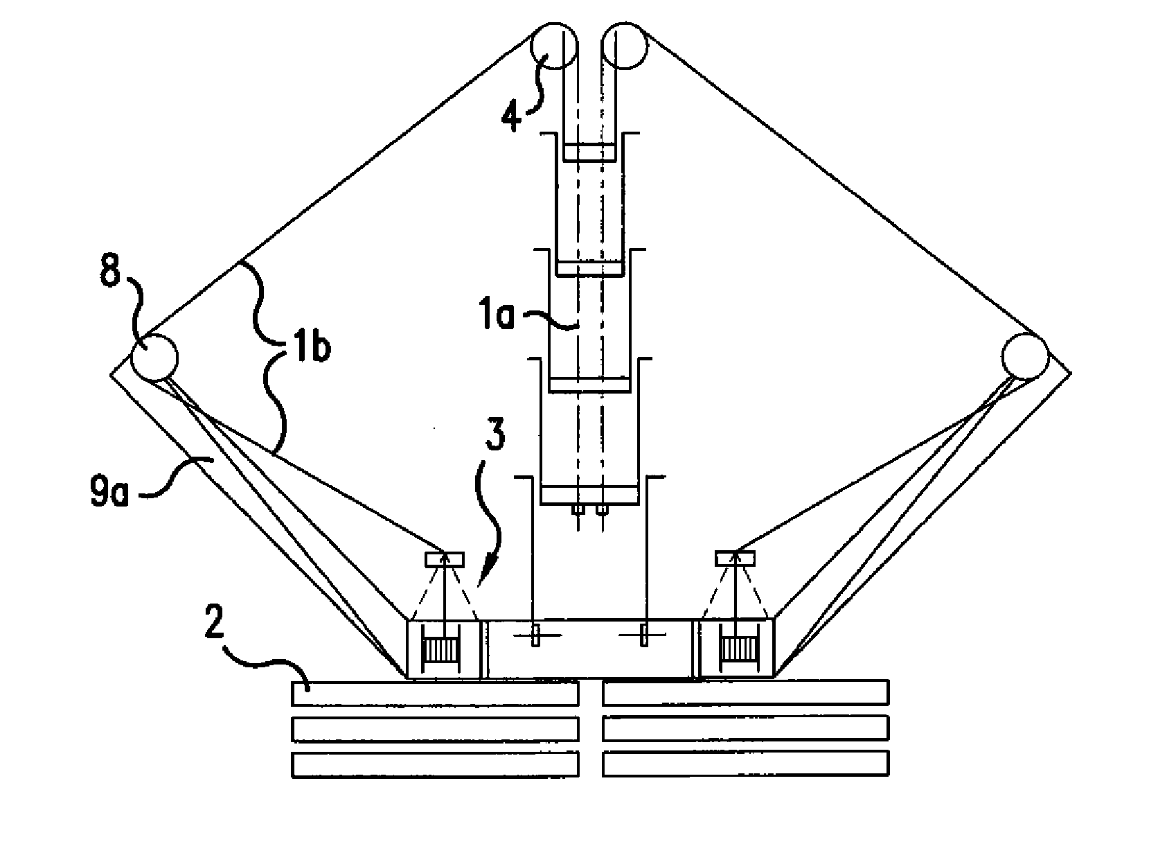
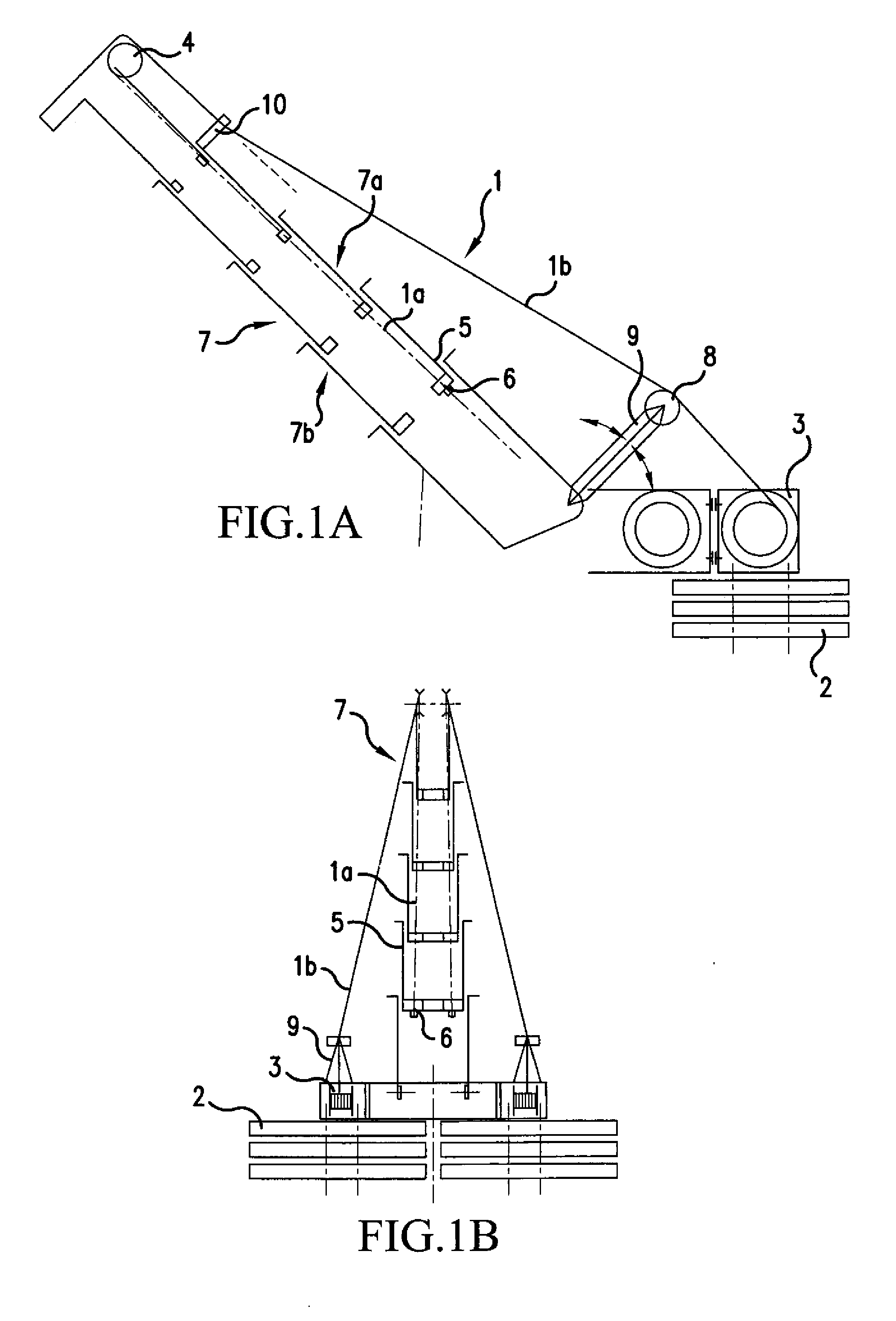
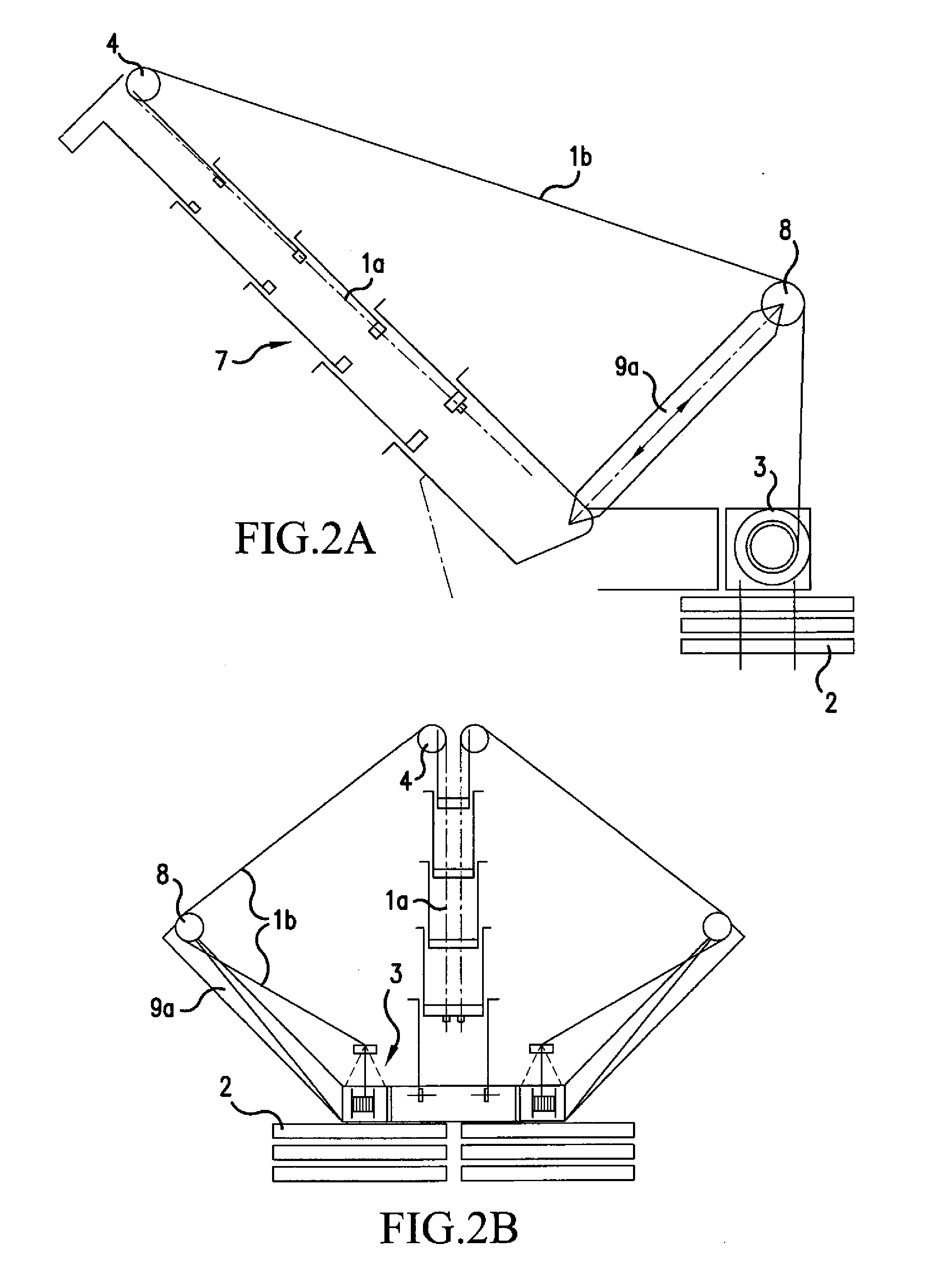
[0032] In the figures, identical reference numerals indicate identical or functionally identical structural unit. FIGS. 1A and 1B show a lateral and a rear view of a telescopic mast for a mobile crane, tensioned on the upper run in accordance with the invention. The telescopic mast 7 and its bracing and biasing system comprising cable winches 3 and counterweights 2 is shown. The mast 7 consists of a number of telescopic portions, of which only the first extending telescopic portion is separately indicated by the reference numeral 5. The lower run of the mast bears the reference numeral 7b and the upper run, which in this case is biased, has the reference numeral 7a.

[0033] The telescopic mast is tensioned towards both sides of the luffing plane, the components in FIG. 1B are only provided with reference numerals on the left-hand side. The tensioning system functions as follows:

[0034] Starting from the cable winch 3, the tensioning cable 1 runs as its outer portion 1b firstly over a...


PUM


Abstract

A tensioning system for a mobile telescopic crane having a telescopic mast includes at least one tensioning cable for bracing the telescopic mast and at least one tensioning winch mounted on the crane superstructure for tensioning the cable. The tension in the cable creates a pressure bias within the mast. The winch is movable with respect to said superstructure of the crane and movement of the winch relative to the superstructure also imposes tension on the tensioning cable.

Description

[0001] This application is a Divisional of co-pending Application Ser. No. 10 / 811,809, filed on Mar. 30, 2004, the entire contents of which are hereby incorporated by reference and for which priority is claimed under 35 U.S.C. §120.BACKGROUND OF THE INVENTION [0002] The present invention relates to a tensioning system for a mobile telescopic crane, in which the telescopic mast is outwardly braced via a tensioning means. In particular, the present invention relates generally to optimally integrating a tensioning system and the components connected to it with a jib design on the superstructure of a mobile telescopic crane. [0003] The aim of any jib design is to keep the ratio of its tare weight to its working load small. The overall system must also exhibit sufficient rigidity to meet the performance capability demanded by the standards. [0004] Jib construction mainly employs fine-grained constructional steel with increasingly higher strengths up to a yield point of 1100 N / mm2. The mo...

Claims


Application Information

Patent Timeline
Patent Type & Authority Applications(United States)
IPC IPC(8): B66C23/42B66C23/60B66C23/687B66C23/70B66C23/82
CPCB66C23/826B66C23/701
Inventor PASCHKE, FRANZ
Owner GROVE US LLC
Why Eureka
Try Eureka