Joist connector

a technology of joists and connectors, applied in the direction of structural elements, building components, construction materials, etc., can solve the problem of determining just how much of the joist is actually anchored to the bearer

Active Publication Date: 2016-01-07
KLEVAKLIP SYST
View PDF13 Cites 18 Cited by
  • Summary
  • Abstract
  • Description
  • Claims
  • Application Information

AI Technical Summary

Benefits of technology

[0007]The present invention is directed to a joist connector, which may at least partially overcome at l

Problems solved by technology

Whilst this is a legal practice, the skew-nailing is often a haphazard practice—as it is done at an angle to the joist and bearer, it is often debatable just how much of the joist is actually anchored to the bearer

Method used


Image

  • Joist connector
  • Joist connector
  • Joist connector

Examples


Embodiment Construction

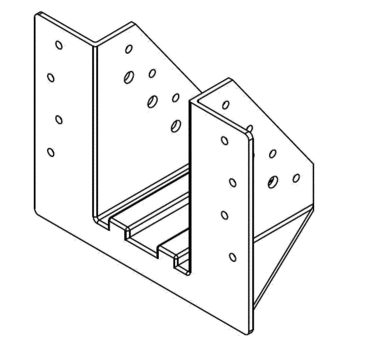
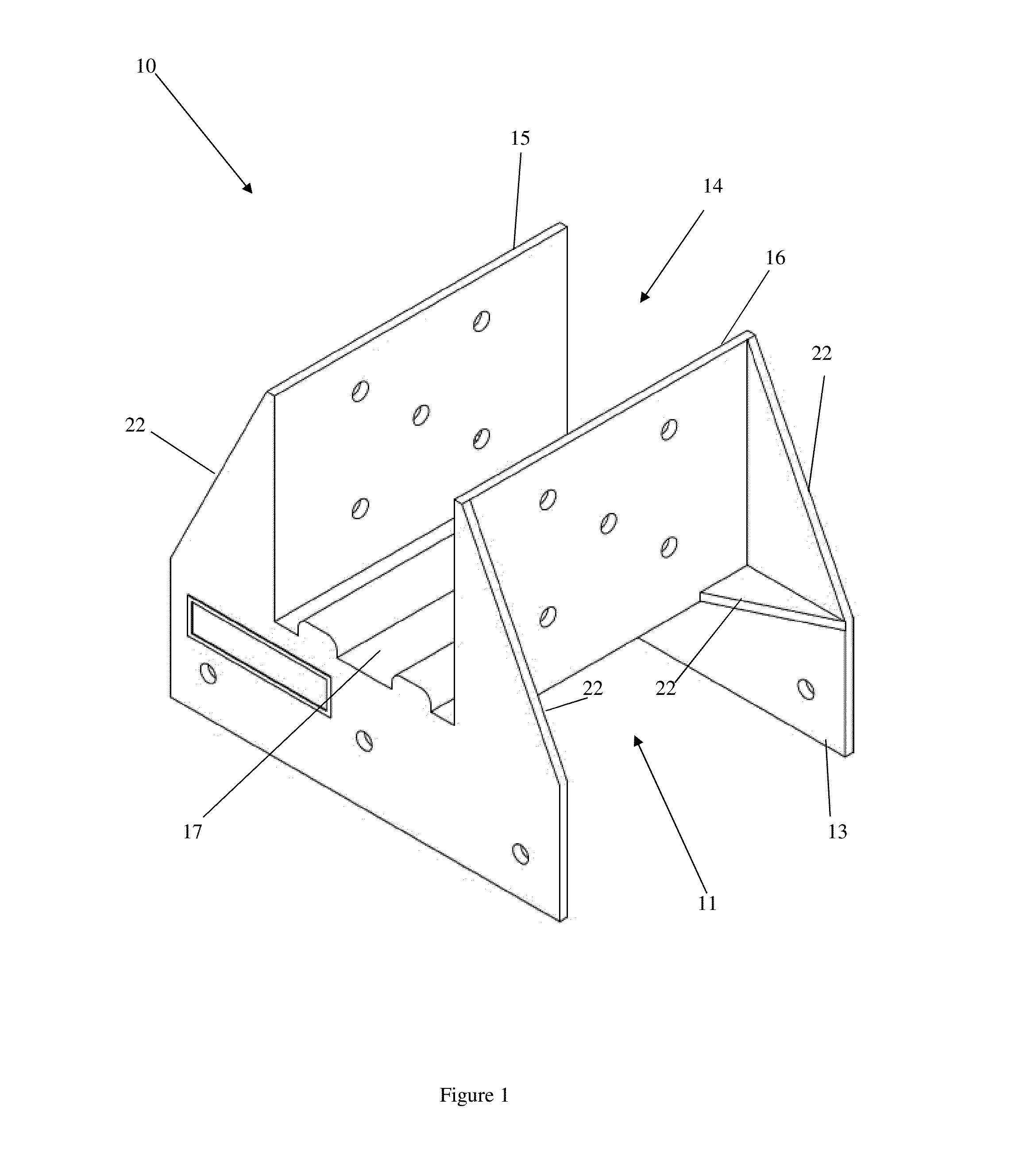
[0052]According to a particularly preferred embodiment of the present invention, a joist connector 10 is provided.

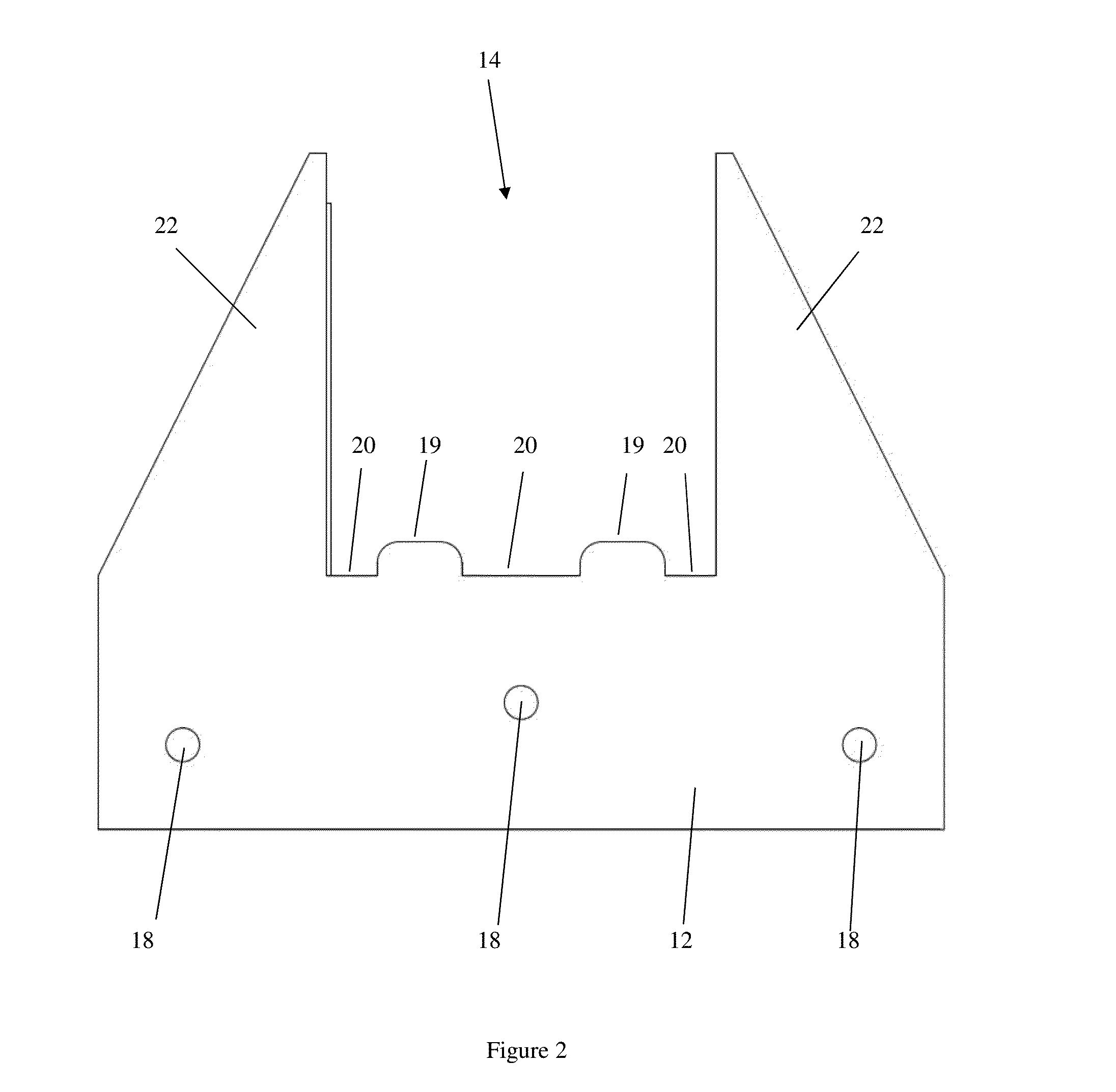
[0053]As illustrated, the joist connector 10 of the preferred configuration includes a unitary body with a first channel 11 defined by two spaced apart flanges 12, 13 and a second channel 14 defined by two spaced apart flanges 15, 16 and which is perpendicular from the first channel 11.

[0054]The joist connector 10 illustrated has a one-piece construction moulded from Nylon 6. The joist connector has been conditioned in order to increase the strength of the material.

[0055]As illustrated, the first channel 11 is substantially perpendicular to the second channel 14 but may be at an angle other than perpendicular if desired. In use, the first channel 11 receives a portion of a beam.

[0056]The pair of flanges 12, 13 defining the first channel 11 are planar and parallel to one another. The flanges 12, 13 are spaced from one another by a standard distance which corresponds to a ...


PUM

PropertyMeasurementUnit
Plasticityaaaaaaaaaa

Abstract

A joist connector including a unitary body with a first channel defined by at least two spaced apart flanges and a second channel defined by at least two spaced apart flanges and offset from the first channel.

Description

CROSS-REFERENCE TO RELATED APPLICATION[0001]This application claims priority under 35 U.S.C. §119(a)-(d) to Australian Patent Application No. AU 2014902579, filed on Jul. 4, 2014, which is hereby incorporated by reference.TECHNICAL FIELD[0002]The present invention relates generally to the field of construction apparatus and particularly to the connection of joists to bearers in a floor support structure.BACKGROUND ART[0003]In most decking situations, a deck built from the ground up contains stumps, bearers, joists and decking boards. It is common practice to bolt the bearers to the stumps and screw the decking boards to the joists. With regards to attaching the joists to the bearers, in some situations, the joists are “hung” inside the bearers using joist hangers. More commonly, the joists sit on top of and at 90 degrees to the bearers.[0004]It is common practice to simply skew-nail the joists to the bearers. Whilst this is a legal practice, the skew-nailing is often a haphazard pra...

Claims


Application Information

Patent Timeline
IPC IPC(8): E04B1/41
CPCE04B1/40E04B2103/04E04B2001/405E04B1/2604E04B1/2612
Inventor DOUPE, GREG JAMESSANDERS, STEPHEN LEY
Owner KLEVAKLIP SYST
Why Eureka
Try Eureka