Transfer device for automobile flexible shaft machining

A technology for automotive flexible shafts and material transfer, which is applied in the direction of transportation and packaging, conveyor objects, rollers, etc., and can solve problems such as flexible shaft bending, reduced processing efficiency, and jamming

Inactive Publication Date: 2020-07-17
陈壮
View PDF5 Cites 0 Cited by
  • Summary
  • Abstract
  • Description
  • Claims
  • Application Information

AI Technical Summary

Problems solved by technology

[0002] Automobile flexible shaft is a necessary accessory on the car. The flexible shaft is a shaft with little rigidity and elasticity that can be freely bent. It is used to connect two shafts with different axes and not in the same direction or with relative motion to transmit rotational motion and torque. , can flexibly transmit the rotational motion and torque to any position. In the automobile flexible shaft production process, the metal end of the flexible shaft needs to be processed. Usually, the flexible shaft is placed on the processing table by a feeding conveyor or manually. Due to the material characteristics of the flexible shaft, it is easy to bend the flexible shaft during the transportation process, resulting in jamming during transportation, and then it cannot enter the designated position correctly. Adjustment will reduce the processing efficiency. Therefore, we propose a material transfer device for automotive flexible shaft processing in order to solve the above-mentioned problems.

Method used


Image

  • Transfer device for automobile flexible shaft machining
  • Transfer device for automobile flexible shaft machining
  • Transfer device for automobile flexible shaft machining

Examples


Embodiment Construction

[0025]In order to make the object, technical solution and advantages of the present invention clearer, the present invention will be further described in detail below in conjunction with the accompanying drawings and embodiments. It should be understood that the specific embodiments described here are only used to explain the present invention, not to limit the present invention.

[0026] In the description of the present invention, it should be noted that the terms "center", "upper", "lower", "left", "right", "front", "rear", "vertical", "horizontal", The orientation or positional relationship indicated by "inner", "outer", etc. is based on the orientation or positional relationship shown in the drawings, and is only for the convenience of describing the present invention and simplifying the description, rather than indicating or implying that the referred device or element must have Certain orientations, constructed and operative in certain orientations, therefore are not to...


PUM


Abstract

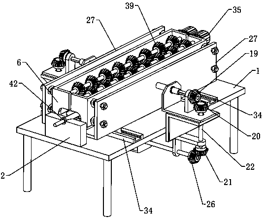
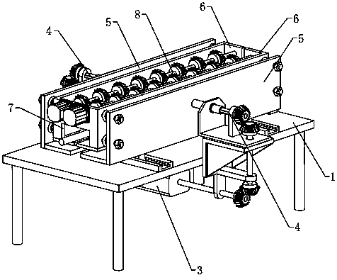
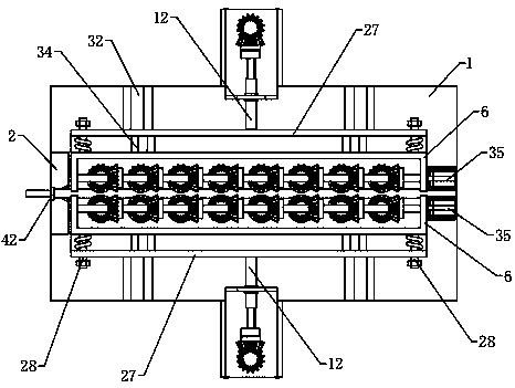
The invention relates to the technical field of automobile flexible shaft machining, in particular to a transfer device for automobile flexible shaft machining. The transfer device comprises a machining table, a positioning table arranged at one end of a table surface of the machining table, a bidirectional translation mechanism, a bidirectional buffering mechanism and a bidirectional abutting rotating mechanism. The bidirectional translation mechanism comprises a synchronous driving assembly and two thread moving assemblies, and the bidirectional buffering mechanism comprises two buffering moving assemblies. The bidirectional abutting rotating mechanism comprises two rectangular boxes, the two adjacent ends of the two rectangular boxes are provided with avoiding accesses for avoiding penetrating of a workpiece, each rectangular box is internally provided with one abutting rotating assembly, each abutting rotating assembly comprises a plurality of sliding wheels which are evenly distributed in the horizontal direction of the corresponding rectangular box and can abut against the workpiece, and the positioning table is provided with a positioning groove used for containing one end of the workpiece. By means of the technical scheme, the flexible shaft can be prevented from being clamped in a conveying process, can be stably conveyed, and stability and machining efficiency are improved.

Description

technical field [0001] The invention relates to the technical field of automobile flexible shaft processing, in particular to a material transfer device for automobile flexible shaft processing. Background technique [0002] Automobile flexible shaft is a necessary accessory on the car. The flexible shaft is a shaft with little rigidity and elasticity that can be freely bent. It is used to connect two shafts with different axes and not in the same direction or with relative motion to transmit rotational motion and torque. , can flexibly transmit the rotational motion and torque to any position. In the automobile flexible shaft production process, the metal end of the flexible shaft needs to be processed. Usually, the flexible shaft is placed on the processing table by a feeding conveyor or manually. Due to the material characteristics of the flexible shaft, it is easy to bend the flexible shaft during the transportation process, resulting in jamming during transportation, an...

Claims


Application Information

Patent Timeline
IPC IPC(8): B65G13/073B65G39/18
CPCB65G13/073B65G39/18
Inventor 陈壮
Owner 陈壮
Why Eureka
Try Eureka