Reduction treatment system applied to high-salt-content wastewater of thermal power plant

A treatment system and high-salt technology, applied in the field of waste water reduction treatment system, can solve the problems of thermal power plant high-salt waste water treatment that needs to be improved, equipment is easy to scale, and energy consumption is high.

Pending Publication Date: 2020-07-17
GUANGDONG DEGA POWER ENVIRONMENTAL PROTECTION TECH CO LTD
View PDF0 Cites 0 Cited by
  • Summary
  • Abstract
  • Description
  • Claims
  • Application Information

AI Technical Summary

Problems solved by technology

At present, the multi-effect evaporation technology and steam mechanical recompression evaporation technology are widely used. The evaporation process consumes a lot of energy, and ...

Method used


Image

  • Reduction treatment system applied to high-salt-content wastewater of thermal power plant

Examples


Embodiment Construction

[0020] Below, the present invention will be further described in conjunction with the accompanying drawings and specific implementation methods. It should be noted that, under the premise of not conflicting, the various embodiments described below or the technical features can be combined arbitrarily to form new embodiments. .

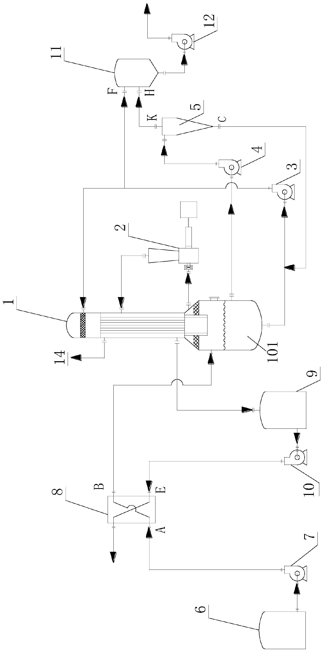
[0021] A system for reducing the amount of high-salt wastewater used in thermal power plants, including a stock solution tank 6, a preheater 8, an evaporator 1, a steam compressor 2, and a hydrocyclone 5. The liquid outlet of the raw liquid tank 6 is connected to the first liquid inlet of the preheater 8 (at A in the figure), and the first liquid outlet of the preheater 8 (at B in the figure) is connected to the bottom liquid chamber of the evaporator 1 101 connections. The liquid stored in the bottom liquid chamber 101 is pumped to the tube side of the evaporator 1 by the circulation pump 3 . The inlet end and the outlet end of the vapor compressor ...


PUM


Abstract

The invention discloses a reduction treatment system applied to high-salt-content wastewater of a thermal power plant. The system comprises a stock solution tank, a preheater, an evaporator, a steam compressor and a hydrocyclone; the liquid outlet end of the stock solution tank is connected with the first liquid inlet end of the preheater; a first liquid outlet end of the preheater is connected with a bottom liquid cavity of the evaporator; liquid stored in the bottom liquid cavity is pumped into a tube pass of the evaporator through a circulating pump; wherein an air inlet end and an air outlet end of the steam compressor are respectively connected with a shell pass of the evaporator, the bottom liquid cavity is connected with a liquid inlet end of the hydrocyclone, and a first liquid outlet end of the hydrocyclone is connected with a liquid inlet end of the circulating pump. In the evaporation and concentration process, although the wastewater is continuously concentrated and reduced, the inner wall of the bottom liquid cavity is not prone to scaling due to the fact that seed crystal balance in the circulating liquid (located in the bottom liquid cavity) is effectively maintained, and the working performance of the evaporator is kept.

Description

technical field [0001] The invention relates to a waste water reduction treatment system, in particular to a waste water reduction treatment system applied to thermal power plants. Background technique [0002] Wastewater from thermal power plants includes domestic sewage and industrial wastewater. The quality of each type of wastewater is different, and the treatment scale is large, difficult, and energy-consuming. With the increasingly stringent national requirements for wastewater discharge standards, "wastewater reduction" and "zero wastewater discharge" will become an irresistible trend. How to effectively treat and reuse wastewater is a common problem faced by thermal power plants. At present, the wastewater treatment systems of most thermal power plants in China can only treat general industrial wastewater and domestic sewage, and have poor treatment effects on high-salt wastewater such as chemical acid-base regeneration high-salt wastewater, fine-treatment regenerati...

Claims


Application Information

Patent Timeline
IPC IPC(8): C02F1/04
CPCC02F1/04C02F1/042
Inventor 吴靓陈卓彬黄震覃涛
Owner GUANGDONG DEGA POWER ENVIRONMENTAL PROTECTION TECH CO LTD
Why Eureka
Try Eureka