
A metallurgical equipment that is convenient for transportation

A technology for metallurgical equipment and gears, applied in the field of metallurgical equipment that is easy to transport, can solve problems such as damage, equipment impact deformation, heavy weight, etc., to avoid gravity inertia impact, reduce equipment damage, and prevent jamming.

Active Publication Date: 2021-12-21
内蒙古包钢西创铁鑫磁材科技有限公司
View PDF6 Cites 0 Cited by
  • Summary
  • Abstract
  • Description
  • Claims
  • Application Information

AI Technical Summary

Problems solved by technology

[0003] In the metallurgical process, since most of the metallurgical raw materials are ore and other materials, due to the heavy weight during the feeding process, it is easy to cause impact deformation or damage to the equipment when feeding

Method used


Image

  • A metallurgical equipment that is convenient for transportation
  • A metallurgical equipment that is convenient for transportation
  • A metallurgical equipment that is convenient for transportation

Examples


Embodiment 1

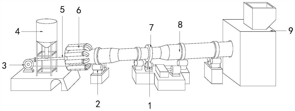
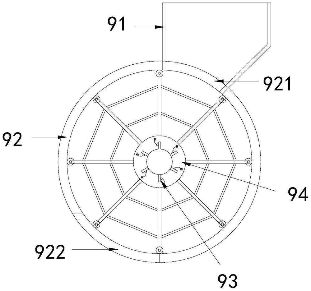
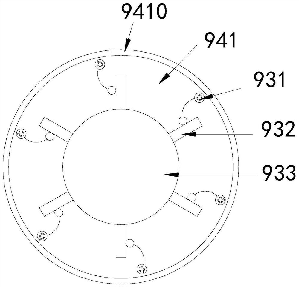
[0028] see Figure 1-5 , the present invention provides a metallurgical equipment technical solution that is convenient for transportation: its structure includes a power unit 1, a supporting wheel 2, a blower 3, a pulverized coal bin 4, a coal injection pipe 5, a cooling cylinder 6, a gear 7, a kiln body 8, a The feeder 9, the gear 7 is wrapped in the middle of the kiln body 8, the gear 7 is connected with the power device 1 at the bottom, the two ends of the kiln body 8 are respectively set on the supporting rollers 2, and the kiln body 8 is inclined, the inlet end of the kiln body 8 is connected to the feeder 9, the outlet end of the kiln body 8 is connected to the blower 3 through the coal injection pipe 5, and the middle of the coal injection pipe 5 is connected to the pulverized coal bin 4 The bottom is connected, and the outlet end of the kiln body 8 is connected with a cooling cylinder 6. The feeder 9 includes a hopper 91, a housing 92, a deceleration structure 93, and...

Embodiment 2

[0031] see Figure 1-6 , the present invention provides a metallurgical equipment technical solution that is convenient for transportation: its structure includes a power unit 1, a supporting wheel 2, a blower 3, a pulverized coal bin 4, a coal injection pipe 5, a cooling cylinder 6, a gear 7, a kiln body 8, a The feeder 9, the gear 7 is wrapped in the middle of the kiln body 8, the gear 7 is connected with the power device 1 at the bottom, the two ends of the kiln body 8 are respectively set on the supporting rollers 2, and the kiln body 8 is inclined, the inlet end of the kiln body 8 is connected to the feeder 9, the outlet end of the kiln body 8 is connected to the blower 3 through the coal injection pipe 5, and the middle of the coal injection pipe 5 is connected to the pulverized coal bin 4 The bottom is connected, and the outlet end of the kiln body 8 is connected with a cooling cylinder 6. The feeder 9 includes a hopper 91, a housing 92, a deceleration structure 93, and...


PUM


Abstract

The invention discloses a kind of metallurgical equipment which is convenient for transportation. Its structure includes a power device, a supporting wheel, a blower, a coal powder bin, a coal injection pipe, a cooling cylinder, a gear, a kiln body, and a feeder. The gear is wrapped in the middle of the kiln body. The gear is connected to the power device at the bottom. The two ends of the kiln body are respectively set on the supporting wheels. The kiln body is inclined. The middle of the coal injection pipe is connected with the bottom of the pulverized coal bin, the outlet of the kiln body is connected with a cooling cylinder, the feeder includes a hopper, a shell, a deceleration structure, and a conveying structure, the bottom of the hopper is connected with the top of the shell, and the shell A conveying structure is installed inside the body, and the beneficial effect of the present invention is: by using the cooperation of the elastic device and the baffle during the ore unloading process, the unloading speed is intermittently decelerated, thereby avoiding the gravity inertial impact of ore unloading and reducing the damage to equipment.

Description

technical field [0001] The invention relates to the field of metallurgical machinery, in particular to a kind of metallurgical equipment convenient for transportation. Background technique [0002] With the rapid development of today's metallurgical industry, the requirements for metallurgical technology and equipment selection are getting higher and higher. Rotary kiln equipment has been widely used in the metallurgical industry. [0003] In the metallurgical process, since metallurgical raw materials are mostly ore and other materials, due to the heavy weight during the feeding process, it is easy to cause impact deformation or damage to the equipment when feeding. Contents of the invention [0004] The main purpose of the present invention is to overcome the deficiencies of the prior art and provide a metallurgical equipment that is convenient for transportation. [0005] The present invention adopts the following technical solutions to achieve: a metallurgical equipme...

Claims


Application Information

Patent Timeline
Patent Type & Authority Patents(China)
IPC IPC(8): F27D3/10
CPCF27D3/0025F27D3/10
Inventor 王志奇
Owner 内蒙古包钢西创铁鑫磁材科技有限公司
Learn More