Falling ball strength experiment device applying photoelectric principle

A technology of falling ball strength and experimental device, which is applied in the direction of measuring device, strength characteristics, transportation and packaging, etc., can solve the problems of manual replacement, high labor intensity and low accuracy of manual detection.

Inactive Publication Date: 2020-07-17
CHANGSHA UNIVERSITY
View PDF0 Cites 1 Cited by
  • Summary
  • Abstract
  • Description
  • Claims
  • Application Information

AI Technical Summary

Problems solved by technology

[0003] When loading and unloading fuel balls in the pebble bed pile, the fuel balls fall from different heights of the loading and unloading system to different parts of the pebble bed, and are impacted to different degrees during the process. If the reactor adopts the method of multiple cycles of fuel balls , then the fuel ball will be hit more, so the spherical fuel element needs to meet certain requirements for falling ball strength; the solution adopted in the related technology is to freely fall the spherical fuel element from a height of four meters to the same material ball bed, and conduct continuous cycle experiments More than 50 times and no obvious damage on the surface (diameter greater than 3mm, depth greater than 1.5mm) is considered qualified; the existing technology currently has low manual detection accuracy, high labor intensity, long detection time, and the need to manually replace damaged detection balls, etc. shortcoming

Method used


Image

  • Falling ball strength experiment device applying photoelectric principle
  • Falling ball strength experiment device applying photoelectric principle
  • Falling ball strength experiment device applying photoelectric principle

Examples


Embodiment Construction

[0018] In order to make the purpose, technical solutions and advantages of the embodiments of the present invention clearer, the technical solutions in the embodiments of the present invention will be clearly and completely described below in conjunction with the drawings in the embodiments of the present invention. Obviously, the described embodiments It is a part of embodiments of the present invention, but not all embodiments. Based on the embodiments of the present invention, all other embodiments obtained by persons of ordinary skill in the art without creative efforts fall within the protection scope of the present invention.

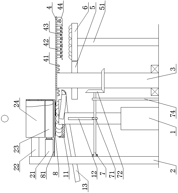
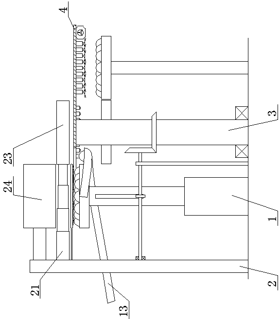
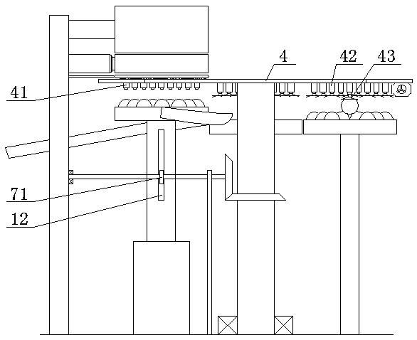
[0019] An experimental device for falling ball strength using the principle of photoelectricity, as shown in the figure, includes a vertically arranged first telescopic rod 1, the fixed end of the first telescopic rod 1 is fixedly installed on the ground, and the top surface of the first telescopic rod 1 is fixed A test ball disc 11 is installed, ...


PUM


Abstract

The invention discloses a falling ball strength experiment device applying a photoelectric principle. The device comprises a first telescopic rod which is vertically arranged; the fixed end of the first telescopic rod is fixedly mounted on the ground; a test ball disc is fixedly mounted on the top surface of the first telescopic rod; a plurality of test balls are placed in the test ball disc; a supporting frame is vertically arranged on one side of the first telescopic rod; a second telescopic rod and a transverse frame are fixedly mounted on the upper part of the supporting frame towards oneside of the first telescopic rod; the movable end of the second telescopic rod faces the first telescopic rod and is fixedly provided with a first annular plate; the end, facing the first telescopic rod, of the transverse frame is fixedly provided with a second annular plate; a rotating shaft is vertically arranged on the other side of the first telescopic rod; and the bottom end of the rotating shaft is connected with a ground bearing. According to the invention, the telescopic rod is used as a main power part, and an ingenious gear linkage structure is adopted; a multi-point laser range finder and a pneumatic grabbing device are matched to achieve the functions of automatic detection and replacement of the detection ball; and compared with an expensive automatic robot, the device is lower in cost and better in reliability.

Description

technical field [0001] The invention belongs to the field of testing the strength of falling balls, in particular to an experimental device for the strength of falling balls using the principle of photoelectricity. Background technique [0002] At present, the spherical fuel element used in my country's pebble bed high-temperature gas-cooled reactor has a diameter of 60mm, and the structure is spherical coated particles (TRISO) dispersed in the graphite matrix of the fuel zone. As the structural material of the fuel element, the matrix graphite enables the coated fuel particles to obtain thermal hydraulic conditions, including transferring heat to the coolant helium, and as a moderator material, it has sufficient moderation ability for fast neutrons, and at the same time It has a certain ability to retain fission products. [0003] When loading and unloading fuel balls in the pebble bed pile, the fuel balls fall from different heights of the loading and unloading system to ...

Claims


Application Information

Patent Timeline
Patent Type & Authority Applications(China)
IPC IPC(8): G01N3/303G01N3/02B65G47/91
CPCB65G47/917B65G47/918G01N3/02G01N3/303G01N2203/0206G01N2203/0252G01N2203/0641G01N2203/0682
Inventor 王丽丽李明亮谭安安熊少琴
Owner CHANGSHA UNIVERSITY
Why Eureka
Try Eureka