Power distribution cabinet heat dissipation device

A heat dissipation device and power distribution cabinet technology, which is applied in substation/power distribution device housing, substation/switchgear cooling/ventilation, substation/switch layout details, etc., can solve the problem of heat dissipation and heat dissipation in multiple parts of power distribution cabinet Limited, single heat dissipation structure of the power distribution cabinet, etc., to achieve the effect of improving heat dissipation efficiency

Inactive Publication Date: 2020-07-17
广东京隆机电设备有限公司
View PDF0 Cites 4 Cited by
  • Summary
  • Abstract
  • Description
  • Claims
  • Application Information

AI Technical Summary

Problems solved by technology

The heat dissipation method of conventional power distribution cabinets is generally set to passive cooling. For the heat generated during the operation of some large The heat dissipation structure in the electric cabinet is relatively simple, and it is difficult to effectively dissipate heat from multiple parts inside the power distribution cabinet, so we need to propose a heat dissipation device for the power distribution cabinet

Method used


Image

  • Power distribution cabinet heat dissipation device
  • Power distribution cabinet heat dissipation device
  • Power distribution cabinet heat dissipation device

Examples


Embodiment Construction

[0016] In order to make the object, technical solution and advantages of the present invention clearer, the present invention will be further described in detail below in conjunction with specific embodiments. It should be understood that the specific embodiments described here are only used to explain the present invention, not to limit the present invention. Based on the embodiments of the present invention, all other embodiments obtained by persons of ordinary skill in the art without making creative efforts belong to the protection scope of the present invention.

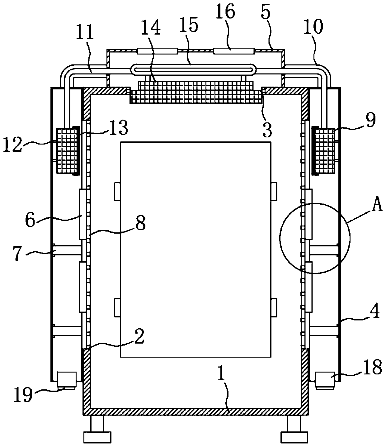
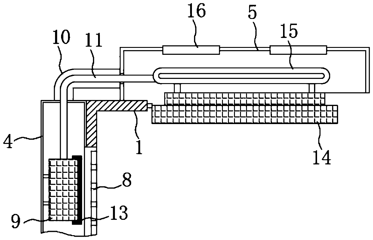
[0017] A heat dissipation device for a power distribution cabinet, comprising a power distribution cabinet 1, a heat conduction chamber 4 and a heat dissipation chamber 5, the heat conduction chamber 4 is fixedly installed at both ends of the power distribution cabinet 1, and the heat dissipation chamber 5 is fixedly installed on the top of the power distribution cabinet 1, A mesh plate 8 is fixedly installed at...


PUM


Abstract

The invention discloses a heat dissipation device of a power distribution cabinet. The device comprises a power distribution cabinet, a heat conduction cavity and a heat dissipation cavity, the two ends of the power distribution cabinet are fixedly provided with heat conduction cavities. The top of the power distribution cabinet is fixedly provided with a heat dissipation cavity. According to thepower distribution cabinet, the heat dissipation structures are arranged at the two ends and the top end of the power distribution cabinet, the heat conduction cavities at the two ends conduct heat ofthe side portion to the top, overall heat dissipation is conducted through the heat dissipation cavity at the top, and therefore heat dissipation is conducted on different positions in the power distribution cabinet. According to the power distribution cabinet heat dissipation device, the heat conduction cavity and the heat dissipation cavity are matched for heat dissipation, so that active heatdissipation is carried out on different parts of the power distribution cabinet, different from a conventional passive heat dissipation mode, and the heat dissipation efficiency of the power distribution cabinet heat dissipation device is improved.

Description

technical field [0001] The invention belongs to the technical field of heat dissipation for a power distribution cabinet, and more specifically relates to a heat dissipation device for a power distribution cabinet. Background technique [0002] Power distribution cabinets are divided into power distribution cabinets, lighting distribution cabinets and metering cabinets, and are the final equipment of the power distribution system. The power distribution cabinet is a general term for the motor control center. The power distribution cabinet is used in the occasions where the load is relatively scattered and there are few circuits, and the motor control center is used in the occasions where the load is concentrated and there are many circuits. They distribute the electric energy of a certain circuit of the upper-level power distribution equipment to the nearest load. This level of equipment shall provide protection, monitoring and control of the load. The first-level power d...

Claims


Application Information

Patent Timeline
IPC IPC(8): H02B1/56H02B1/28H02B1/30
CPCH02B1/28H02B1/30H02B1/306H02B1/565
Inventor 袁富国袁彩丽
Owner 广东京隆机电设备有限公司
Why Eureka
Try Eureka