Battery module for improving charging rate and efficiency of terminal equipment and working method thereof

A battery module and charging rate technology, which is applied to battery circuit devices, measuring power, and current collectors. It can solve problems such as long charging time, battery temperature rise, and charging heat, and achieves the contradiction between heating, improving charging speed, and The effect of reducing the charging current

Inactive Publication Date: 2020-07-17
NORTHWEST UNIV
View PDF6 Cites 3 Cited by
  • Summary
  • Abstract
  • Description
  • Claims
  • Application Information

AI Technical Summary

Problems solved by technology

[0002] At present, the functions of terminal devices are becoming more and more abundant, and the demand for battery capacity is getting higher and higher, so the requirements for charging speed of terminal devices are also getting higher and higher, otherwise it will lead to long charging time and seriously affect the user experience
[0003] The existing fast charging methods for terminal equipment basically use high-voltage charging, high-current direct charging, etc., but they all face serious charging heating problems.
Because the battery has a certain internal resistance, and the current entering the battery during fast charging is relatively large, the power consumption consumed by the internal resistance will also be relatively large, resulting in low charging efficiency and rapid rise in battery temperature, which causes the device to heat up
In order to reduce the heating problem of the device, after charging the battery with a high current for a period of time, the charging current must be reduced to control the heating, resulting in a limited duration of fast charging, and the advantages of fast charging cannot be fully utilized
[0004] The output voltage of most batteries in the existing terminal equipment is between 3 and 5V, and the output voltage is single, only one voltage value can be output, and the application flexibility is not enough

Method used


Image

  • Battery module for improving charging rate and efficiency of terminal equipment and working method thereof
  • Battery module for improving charging rate and efficiency of terminal equipment and working method thereof
  • Battery module for improving charging rate and efficiency of terminal equipment and working method thereof

Examples


Embodiment Construction

[0024] The present invention will be further described in detail below with reference to specific embodiments, but it is not intended to limit the present invention.

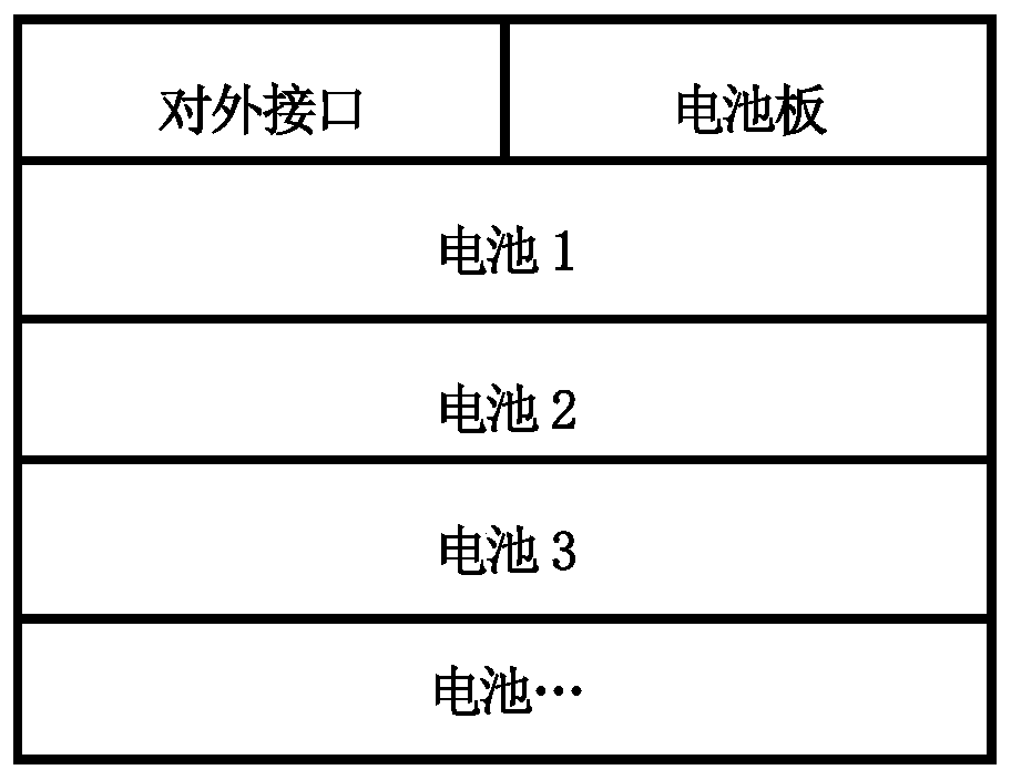
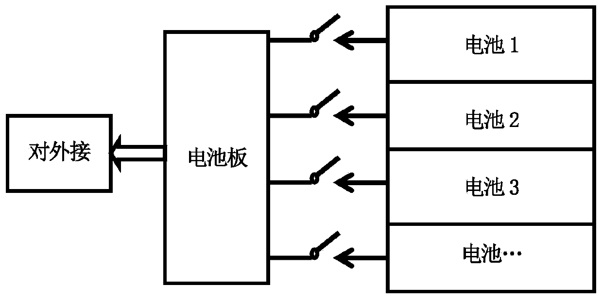
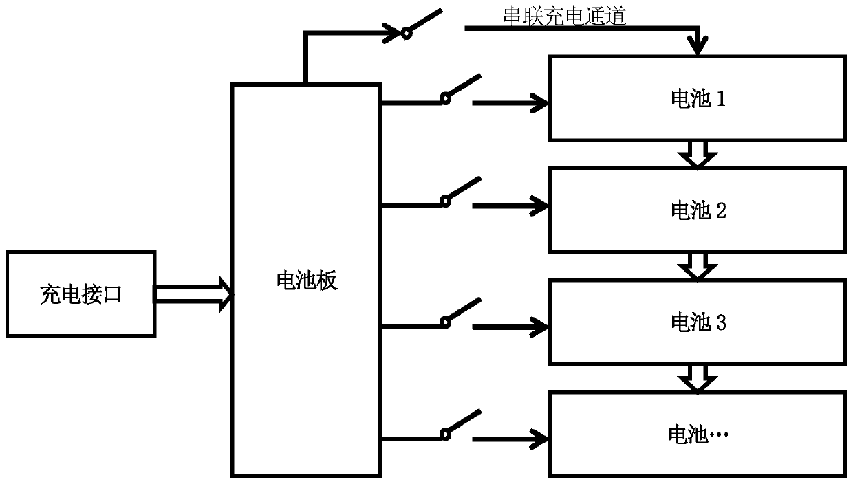
[0025] Such as figure 1 As shown, the battery module of the present invention includes a battery pack composed of several batteries, a battery board and an external interface provided on the battery board; taking a lithium battery module as an example, a lithium battery module contains exactly the same multiple pieces of lithium For batteries, the output voltage of each internal battery is consistent with the voltage required by the terminal equipment. It is recommended to use 2-3 batteries to form a battery pack in a package. The current, output voltage and internal resistance of each battery in the battery pack are completely consistent. The external interfaces of each battery are unified into one group.

[0026] The external interface includes battery output positive, battery negative, battery ID pin, and battery ...


PUM


Abstract

The invention discloses a battery module for improving the charging rate and efficiency of terminal equipment and a working method of the battery modulethereof. The battery module comprises a batterypack composed of a plurality of identical batteries, a battery panel and an external interface. Power supply output management, charging management, electric quantity detection, battery switch controland charging and power supply path switching of the battery module are carried out through a the power supply management circuit on the battery panel. During early-stage high-voltage charging, the batteries are connected in series. T, the charging current of each battery is reduced , and the thermal power consumption of the battery is greatly reduced, so that the heating of the battery is reduced, the contradiction between quick charging and heating is solved, the charging speed of the battery module is increased, the user experience of the terminal equipment is improved, the battery module supports the output of various voltages, and the battery is more flexible to use.

Description

Technical field [0001] The present invention relates to electronic device charging technology, in particular to a battery module and its working method for improving the charging rate and efficiency of terminal devices. Background technique [0002] At present, the functions of terminal devices are becoming more and more abundant, and the requirements for battery capacity are getting higher and higher, so the requirements for charging speed of the terminal devices are becoming higher and higher, otherwise it will lead to too long charging time and seriously affect the user experience. [0003] The existing fast charging methods of terminal equipment basically adopt high-voltage charging, high-current direct charging, etc., but they all face serious charging and heating problems. Because the battery has a certain internal resistance, and the current that enters the battery during fast charging is relatively large, the power consumption of the internal resistance will also be relativ...

Claims


Application Information

Patent Timeline
Patent Type & Authority Applications(China)
IPC IPC(8): H02J7/00G01R31/385G01R31/396
CPCG01R31/385G01R31/396
Inventor 雷晓艺梁晓祯戴扬张云尧张涵闫军锋赵武张志勇
Owner NORTHWEST UNIV
Why Eureka
Try Eureka