
Power utilization data acquisition and control device

A technology of control device and power consumption data, which is applied to circuit devices, boards/panels/desks of substations/switch devices, electrical components, etc. It is difficult for professional and technical personnel to install and other problems, so as to achieve the effect of automatic monitoring and automatic power-off, and to prevent the transmission of household electrical fires.

Pending Publication Date: 2020-07-17
智慧式有限公司
View PDF8 Cites 0 Cited by
  • Summary
  • Abstract
  • Description
  • Claims
  • Application Information

AI Technical Summary

Problems solved by technology

[0002] 1. The traditional air switch senses the magnitude of the current physically, and controls the mechanical shrapnel switch through the current conductor to cut off the power. The traditional air switch has very weak perception of current and residual current when there is weak leakage or electric shock, so these two types Under such circumstances, it is extremely difficult for the air switch to automatically cut off the power, which cannot effectively solve the occurrence of electric shock casualties;
[0003] 2. Lack of detection of wire temperature, lack of calculation and judgment of power when all electrical appliances in the home are turned on, temperature rise caused by wire overload will also lead to electrical fires in the home, and the air switch cannot solve this problem;
[0004] 3. The traditional air switch is completely mechanically controlled, lacks the function of material network, and cannot realize linkage with other fire detection equipment, especially in the case of a home fire that needs to be powered off, the traditional air switch cannot meet the requirements of timely power off;
[0005] 4. The traditional air switch cannot realize the detection voltage, no matter the voltage is high or low, it will only work in a fixed manner. When the voltage is unstable, it is necessary to install a voltage stabilizer at the lower end of the power line to achieve voltage stabilization. It cannot solve the problem of electrical burnout when the voltage fluctuates. hidden dangers;
[0006] 5. The traditional air switch does not have the function of remote power-off, and the continuous power-on operation of household appliances will also cause fire hazards. The lack of remote power-off function will make household electricity use less controllable, and users cannot quickly power off independently;
[0007] 6. At present, the leakage and electric shock in the home are mostly solved by the leakage protector, but the data of the leakage protector is fixed due to the different consumption of the household line. It is convenient and cannot be used in conjunction with the air switch. At present, there is an air switch integrated with the leakage protector and the air switch, but it cannot effectively detect the weak leakage. time, the health and safety of the electric shock personnel cannot be effectively protected, and there is still the possibility of death;
[0008] 7. At present, the equipment that can realize electrical fire detection in the home is large in size and cannot be installed in the home distribution box. Even if it is installed, it cannot reduce the number of original air switches. Correct installation takes a long time to install, and the function and fault self-testing of accessories cannot be realized;
[0009] 8. The existing technology detects electrical circuit data using external current transformers, residual current transformers, temperature sensors and other equipment, which are large in size and difficult to integrate and install in a small device and realize the corresponding data collection function

Method used


Image

  • Power utilization data acquisition and control device
  • Power utilization data acquisition and control device
  • Power utilization data acquisition and control device

Examples


Embodiment Construction

[0035] The following will clearly and completely describe the technical solutions in the embodiments of the present invention with reference to the accompanying drawings in the embodiments of the present invention. Obviously, the described embodiments are only some, not all, embodiments of the present invention.

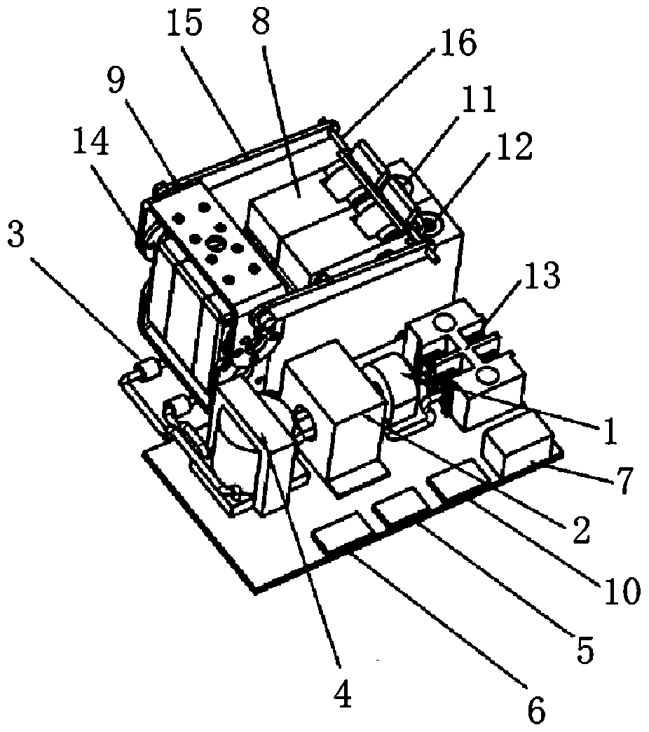
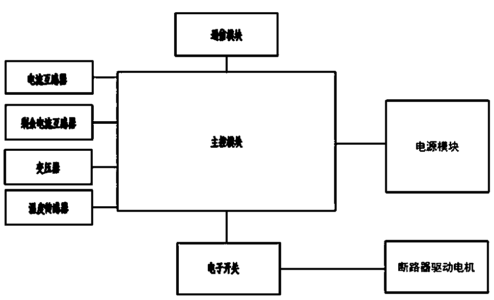
[0036] refer to Figure 1-5 , a kind of electricity data acquisition and control device, comprises current transformer 1, and one side of current transformer 1 is provided with residual current transformer 2, and one side of residual current transformer 2 is provided with temperature sensor 3, and residual current transformer 2 A transformer 4 is provided on the side away from the current transformer 1, and a main control module 5, a communication module 6, an electronic switch 7 and a power supply module 10 are arranged in sequence on the same side of the current transformer 1, the residual current transformer 2 and the transformer 4, One side of the temperature sen...


PUM


Abstract

The invention belongs to the field of wireless data transmission, and particularly provides a power utilization data acquisition and control device. Proposed now is the following scheme: the power utilization data acquisition and control device comprises a current transformer, a residual current transformer is arranged on one side of the current transformer; a temperature sensor is arranged on oneside of the residual current transformer; a transformer is arranged on one side, far away from the current transformer, of the residual current transformer; a main control module, a communication module, an electronic switch and a power module are sequentially arranged on the same side of the current transformer, the residual current transformer and the transformer, a circuit breaker and a circuit breaker driving motor are arranged on one side of the temperature sensor, and an electric appliance wiring terminal set is arranged on the side, away from the residual current transformer, of the current transformer. Household electrical fire disasters are prevented, automatic monitoring and automatic power-off are realized, fast breaking within 0.5s can be realized, death accidents caused by electric leakage or electric shock of personnel can be avoided in an environment of 220V household electricity, and integration of remote power-off and remote switch-on is realized.

Description

technical field [0001] The invention relates to the technical field of wireless data transmission, in particular to a power consumption data collection and control device. Background technique [0002] 1. The traditional air switch senses the magnitude of the current physically, and controls the mechanical shrapnel switch through the current conductor to cut off the power. The traditional air switch has very weak perception of current and residual current when there is weak leakage or electric shock, so these two types Under the circumstances, it is extremely difficult for the air switch to automatically cut off the power, and it cannot effectively solve the occurrence of electric shock casualties; [0003] 2. Lack of detection of wire temperature, lack of calculation and judgment of power when all electrical appliances in the home are turned on, temperature rise caused by wire overload will also lead to electrical fires in the home, and the air switch cannot solve this prob...

Claims


Application Information

Patent Timeline
IPC IPC(8): H02J13/00H02B1/04
CPCH02B1/04
Inventor 江正云
Owner 智慧式有限公司
Learn More