Regional atmospheric pollutant suction equipment group and method for treating atmospheric pollutants

A technology of air pollutants and equipment groups, applied in chemical instruments and methods, gas treatment, separation methods, etc., can solve problems such as difficult artificial control of air pollution

Inactive Publication Date: 2020-07-21
谭烨
View PDF0 Cites 0 Cited by
  • Summary
  • Abstract
  • Description
  • Claims
  • Application Information

AI Technical Summary

Problems solved by technology

[0003] In order to solve the problem that it is difficult to artificially control air pollution in the prior art, the present invention provides a set of regional air pollutant suction equipment and a method for controlling air pollutants. The ground area of ​​the effective pollution suction area ( figure 2 ) above the sewage suction equipment group, to control the pollutants in the working volume, create a low concentration area of ​​pollutants (49), use the concentration difference (48) to attract and guide the pollutants in the high concentration area (50), to the equipment working area The treated low-concentration area (49) diffuses and flows (47), and the equipment continues to treat the pollutants that diffuse and flow into the working volume (4, 9, 17, 13), reducing the pollutants in the high-concentration area (21) content, so that the artificial output of pollutants in the polluted area and the natural output are close to greater than or equal to the input, and the regional air pollutants are diluted to achieve the suppression or control of air pollution

Method used


Image

  • Regional atmospheric pollutant suction equipment group and method for treating atmospheric pollutants
  • Regional atmospheric pollutant suction equipment group and method for treating atmospheric pollutants
  • Regional atmospheric pollutant suction equipment group and method for treating atmospheric pollutants

Examples


Embodiment Construction

[0100] In order to make the purpose, technical solutions and advantages of the embodiments of the present invention clearer, the technical solutions in the embodiments of the present invention will be clearly and completely described below in conjunction with the drawings in the embodiments of the present invention. Obviously, the described embodiments It is only some embodiments of the present invention, but not all embodiments. Based on the embodiments of the present invention, all other embodiments obtained by persons of ordinary skill in the art without creative efforts fall within the protection scope of the present invention.

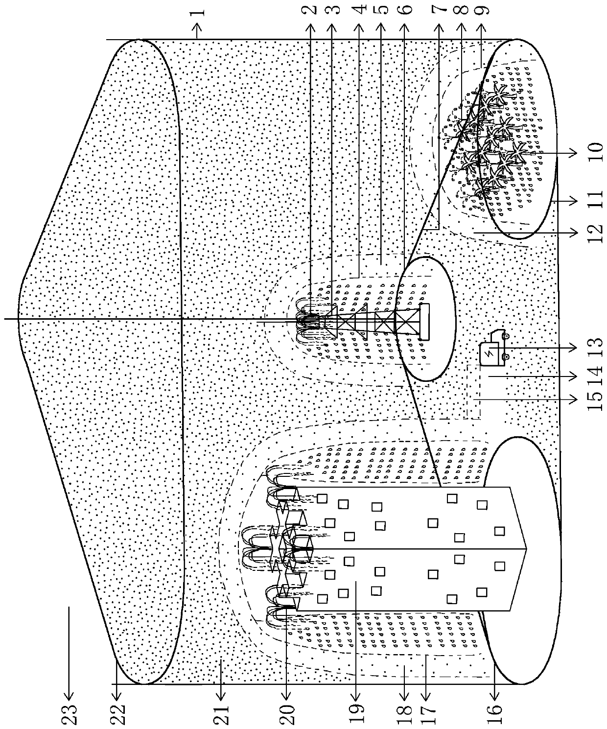
[0101] In the area to be treated (1), it is preferable to place the equipment at the pollution source, that is, the city, and the effective sewage suction area has a ground area greater than 0.0624 square kilometers ( figure 2 ); preferably refer to the historical pollution record data; preferably build multiple high-efficiency sewage suction poin...


PUM


Abstract

The invention relates to an equipment group for treating regional atmospheric pollutants and a treatment method for the atmospheric pollutants. A plurality of pieces of water spraying equipment/pollution treatment equipment are arranged on the effective pollution absorption area in the pollution area to form pollution absorption point positions; ground features, terrain difference and vegetation are used, the falling height difference is increased, and the working size is increased; the extra voltage of the sprayed water is increased by using a charging technology; the treatment efficiency isimproved by using mobile and semi-mobile point locations; a control system is used for controlling and coordinating the equipment working state; pollutants in a high-concentration polluted space outside a water spraying range are attracted and guided to diffuse and flow into the low-concentration polluted space in the water spraying range by utilizing a pollutant low-concentration area created ata pollutant suction point position, so that the atmospheric pollutants are treated and diluted by matching manual output with natural output which is approximately greater than or equal to pollutant input.

Description

technical field [0001] The invention relates to a device and a method for controlling air pollutants, in particular to an equipment group and a method for controlling regional air pollutants. Background technique [0002] Existing technologies, the first one is to force the polluted air to flow through the equipment through power in situ, and carry out air treatment on the atmosphere, but this requires a lot of cost; the second technology is to use chemical substances to spray over the area, and then achieve Control pollutants, but have a greater impact on the environment and society; the third technology is a conceptual method, that is, to achieve the effect of pollution control by controlling input, but many air polluted areas are cities in developing countries, and there are many social constraints. The existing technology is difficult to break through in terms of equipment volume, initial investment, operating cost, energy consumption, and work efficiency, and it is dif...

Claims


Application Information

Patent Timeline
Patent Type & Authority Applications(China)
IPC IPC(8): B01D47/06B01D53/18
CPCB01D47/063B01D53/14B01D53/18B01D2258/06
Inventor 不公告发明人
Owner 谭烨
Why Eureka
Try Eureka