
Die holder locking device of extruding machine

A technology of locking device and extruding machine, which is applied in the direction of motor vehicles, load fixing, transportation and packaging, etc. It can solve the problems of increasing production cost, vibration of the mold, damage of the base, etc., and achieves the effect of increasing safety and reducing safety accidents

Inactive Publication Date: 2020-07-21
重庆珂玥模具有限公司
View PDF8 Cites 2 Cited by
  • Summary
  • Abstract
  • Description
  • Claims
  • Application Information

AI Technical Summary

Problems solved by technology

[0002] The traditional mold is in direct contact with the ground. When the mold is moved, the mold is moved by friction with the ground. It needs to pull the mold with a large force on the fixed chain, which makes it very difficult to move the mold.
[0003] In addition, when the current mold passes through the uneven ground during the moving process, the mold will vibrate, which will drive the equipment on the base to vibrate, and then cause vibration to the components in the mold, causing the components in the mold to change in position, etc. It affects the safety of the mold. When moving the mold through the fixed chain, the existing method is to directly contact the fixed chain with the hook on the base, and directly pull the base, which makes it very easy to damage the base when pulling the base. , Moreover, when moving many molds, each mold is equipped with a hook that cooperates with the fixed chain, which undoubtedly increases the production cost

Method used


Image

  • Die holder locking device of extruding machine
  • Die holder locking device of extruding machine
  • Die holder locking device of extruding machine

Examples


Embodiment Construction

[0025] In order to make the above objects, features and advantages of the present invention more comprehensible, specific implementations of the present invention will be described in detail below in conjunction with the accompanying drawings. In the following description, numerous specific details are set forth in order to provide a thorough understanding of the present invention. However, the present invention can be implemented in many other ways different from those described here, and those skilled in the art can make similar improvements without departing from the connotation of the present invention, so the present invention is not limited by the specific implementations disclosed below.

[0026] It should be noted that when an element is referred to as being “fixed” to another element, it can be directly on the other element or there can also be an intervening element. When an element is referred to as being "connected to" another element, it can be directly connected ...


PUM


Abstract

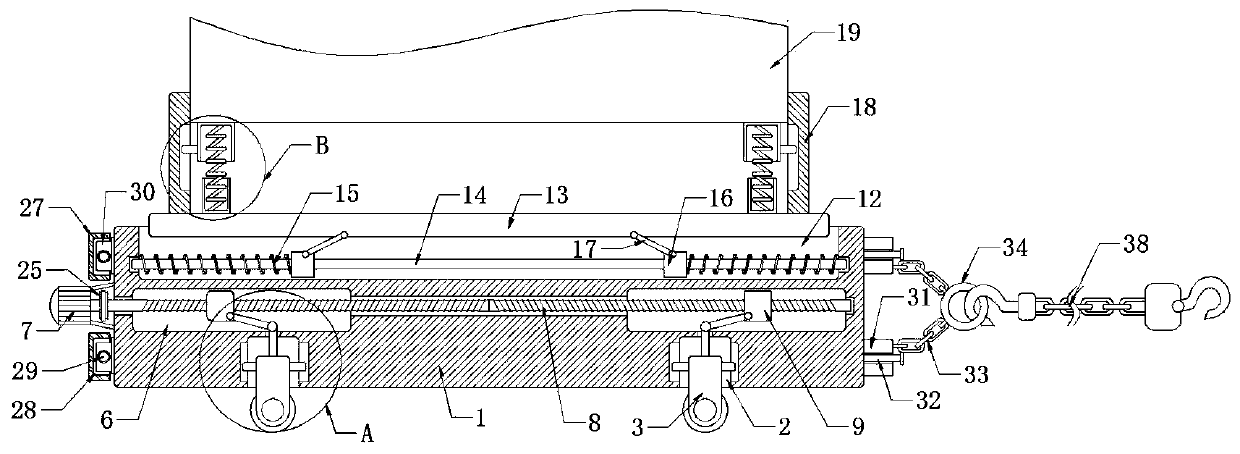
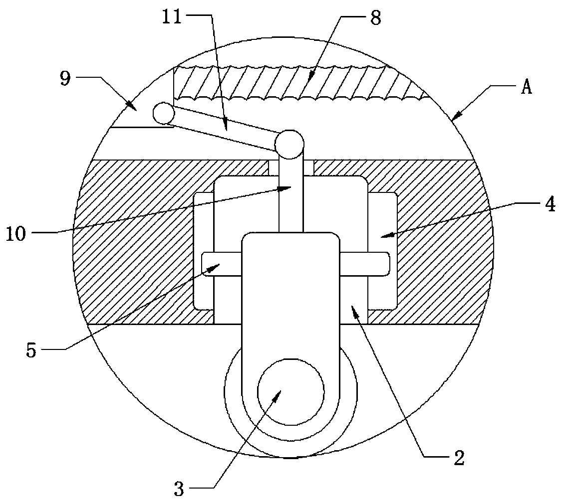
The invention discloses a die holder locking device of an extruding machine. The device comprises a die holder; four first grooves are symmetrically formed in the lower end of the die holder; universal wheels are arranged in the four first grooves; first sliding grooves are formed in the opposite inner walls of the first grooves; the inner walls of the first sliding grooves are fixedly connected with the side walls of universal wheels through first connecting blocks; four second grooves are symmetrically formed in the side wall of the die holder; the four second grooves correspond to the fourfirst grooves; and first driving devices for driving the universal wheels to slide in the first grooves are installed in the second grooves. By arranging a second double-end threaded rod, a second lead screw nut, a first clamping plate and a second clamping plate, the fixed lock chain can be matched with a pull ring on the side wall of the second clamping plate to move the die holder, the fixed lock chain is prevented from being directly connected with a hook on the die holder, and the die holder is not easy to damage.

Description

technical field [0001] The invention relates to the technical field of molds, in particular to a locking device for an extruder mold base. Background technique [0002] The traditional mold is in direct contact with the ground. When the mold is moved, the mold is moved by friction with the ground. It needs to pull the mold with a large force on the fixed chain, which makes it very difficult to move the mold. . [0003] In addition, when the current mold passes through the uneven ground during the moving process, the mold will vibrate, which will drive the equipment on the base to vibrate, and then cause vibration to the components in the mold, causing the components in the mold to change in position, etc. It affects the safety of the mold. When moving the mold through the fixed chain, the existing method is to directly contact the fixed chain with the hook on the base, and directly pull the base, which makes it very easy to damage the base when pulling the base. , And, whe...

Claims


Application Information

Patent Timeline
Patent Type & Authority Applications(China)
IPC IPC(8): B62D59/00B60B33/06B60P7/08B60P7/16B60D1/18
CPCB60B33/063B60D1/18B60P7/0892B60P7/16B62D59/00
Inventor 许东山
Owner 重庆珂玥模具有限公司
Learn More