A small needle knife structure for treating osteoarthropathy

A technique for osteoarthritis and acupotomy, applied in the medical field, can solve the problems of inconvenient use, poor use effect, and replacement of needle bars when a small needle knife cannot be used, and achieves the effect of convenient operation and avoiding accidental injury

Active Publication Date: 2020-07-24
SHANDONG QINGDAO HOSPITAL OF INTEGRATED TRADITIONAL & WESTERN MEDICINE
View PDF8 Cites 2 Cited by
  • Summary
  • Abstract
  • Description
  • Claims
  • Application Information

AI Technical Summary

Problems solved by technology

[0004] The present invention proposes a small needle knife structure for treating osteoarthritis, which solves the problem that the existing small needle knife cannot be replaced according to the use situation, is not convenient enough to use, and has poor use effect

Method used


Image

  • A small needle knife structure for treating osteoarthropathy
  • A small needle knife structure for treating osteoarthropathy
  • A small needle knife structure for treating osteoarthropathy

Examples


Embodiment 1

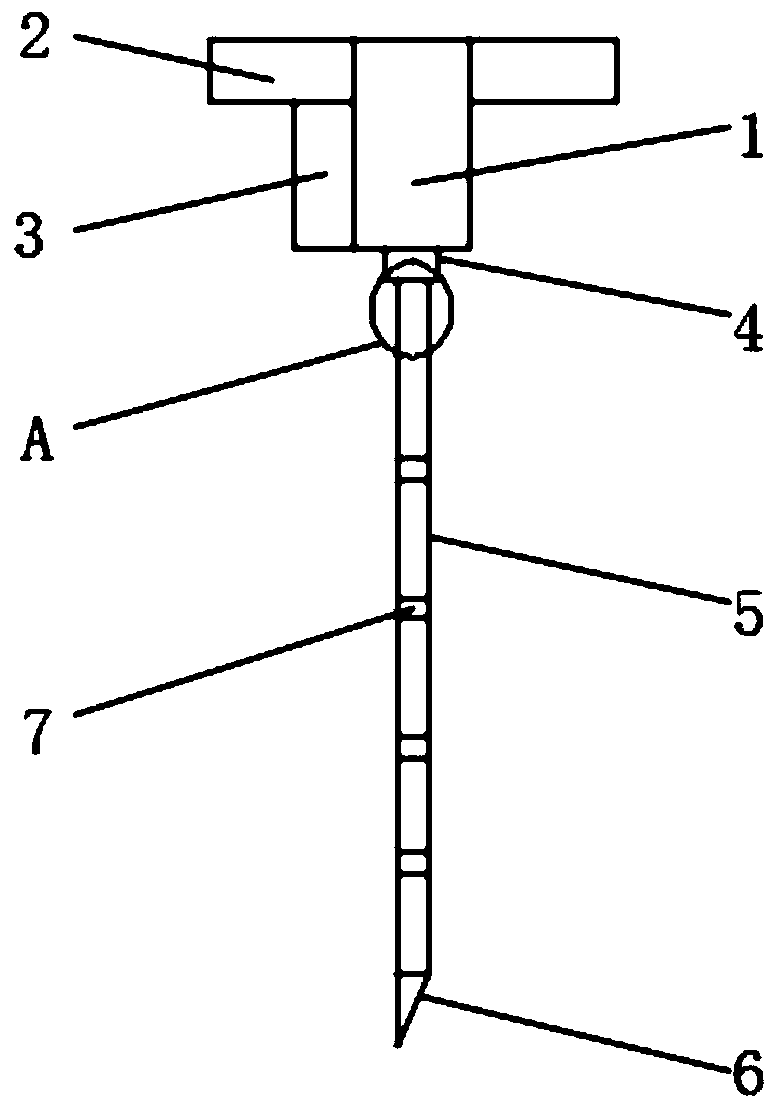
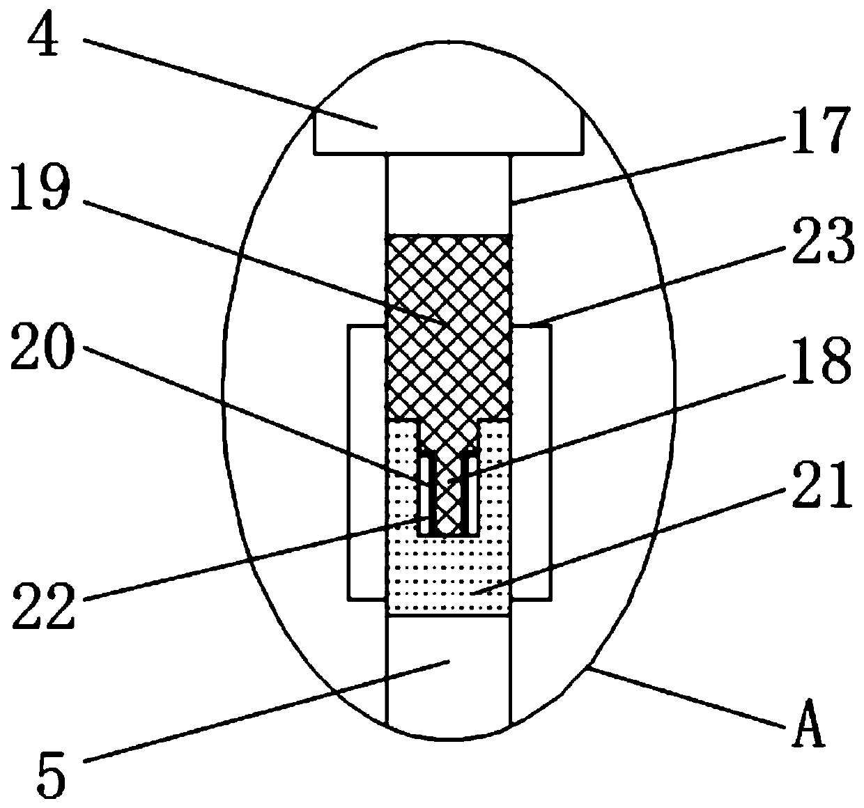
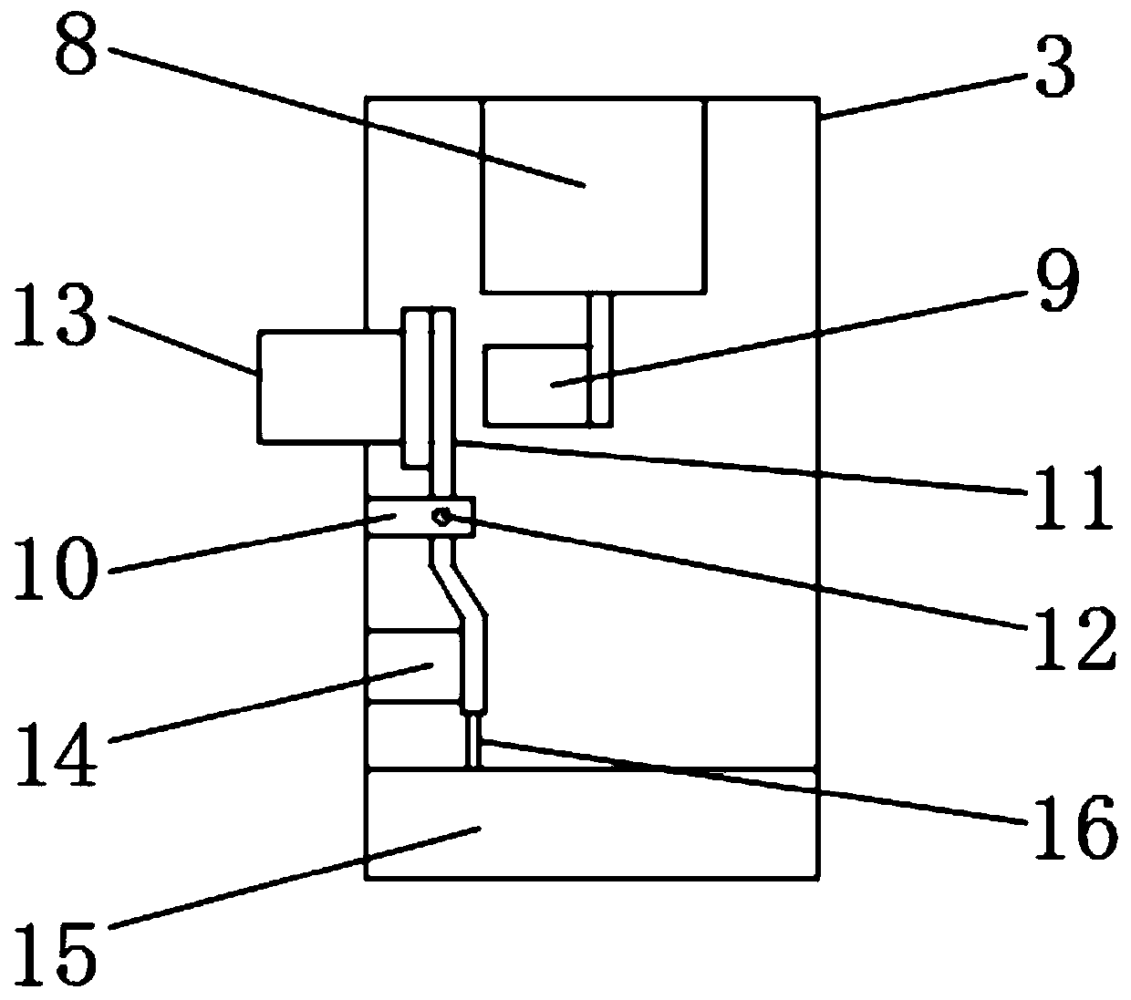
[0024] refer to Figure 1-3 , a small needle-knife structure for treating osteoarthritis, comprising a knife handle 1 and a needle bar 5, connecting plates 2 are fixedly installed on both sides of the upper end of the knife handle 1, and the outer surface of one side of the knife handle 1 is located on the connecting plate 2 A light tube 3 is fixedly installed at the lower end of the knife handle 1, a connecting seat 4 is fixedly installed in the middle of the lower end of the handle 1, a knife head 6 is fixedly connected to the lower end of the needle bar 5, a scale bar 7 is drawn on the outer surface of the needle bar 5, and the light tube The inner front end of 3 is fixedly installed with laser lamp body 8, the outer surface of the rear end of laser lamp body 8 is located at the position inside the lamp tube 3 and is fixedly connected with metal contact 9, and the inner side of lamp tube 3 is fixedly installed with fixing frame 10 One end of the fixed frame 10 is movably co...

Embodiment 2

[0031] refer to Figure 1-4, a small needle-knife structure for treating osteoarthritis, comprising a knife handle 1 and a needle bar 5, connecting plates 2 are fixedly installed on both sides of the upper end of the knife handle 1, and the outer surface of one side of the knife handle 1 is located on the connecting plate 2 A light tube 3 is fixedly installed at the lower end of the knife handle 1, a connecting seat 4 is fixedly installed in the middle of the lower end of the handle 1, a knife head 6 is fixedly connected to the lower end of the needle bar 5, a scale bar 7 is drawn on the outer surface of the needle bar 5, and the light tube The inner front end of 3 is fixedly installed with laser lamp body 8, the outer surface of the rear end of laser lamp body 8 is located at the position inside the lamp tube 3 and is fixedly connected with metal contact 9, and the inner side of lamp tube 3 is fixedly installed with fixing frame 10 One end of the fixed frame 10 is movably con...


PUM


Abstract

The invention belongs to the medical field, and in particular to a small needle knife structure for treating osteoarthropathy. Aiming at the problems that the existing small needle knife can not be replaced according to the use condition, not convenient to use, and the use effect is not good. The small needle knife includes a knife handle and a needle bar, and connecting plates are fixedly installed on both sides of the upper end of the knife handle. A light tube is fixedly installed on one side of the outer surface of the knife handle at the lower end of the connecting plate. A connecting seat is fixedly installed in the middle of the lower end of the knife handle. The lower end of the needle bar is fixedly connected with a cutter head, the outer surface of the needle bar is engraved witha scale bar, and the inner front end of the lamp tube is fixedly provided with a laser lamp body. The invention can quickly and conveniently replace the needle bar according to the use situation, makes the small needle knife more convenient to use, and can be illuminated by a laser light when in use, thereby being convenient for the use of the small needle knife and at the same time improving theaccuracy of the use of the small acupuncture knife.

Description

technical field [0001] The invention relates to the field of medical technology, in particular to a small needle-knife structure for treating osteoarthritis. Background technique [0002] The small needle knife looks like an acupuncture needle, but it has a narrow blade at the tip, which can play the dual functions of acupuncture and knife cutting. instrument. During the treatment of osteoarthritis, the small needle knife can not only perform acupuncture therapy on the bone joint, but also combine with Western medicine to cut the tissue of the bone joint through the small needle knife, so as to facilitate the treatment of osteoarthrosis . [0003] The existing small needle-knife structure has certain defects in use. The small needle-knife structure is inconvenient to replace the needle bar. The small acupotomy is not convenient to use, and the function of the small acupotomy is relatively single. When using it, it cannot supplement the light on the treatment part, which i...

Claims


Application Information

Patent Timeline
Patent Type & Authority Applications(China)
IPC IPC(8): A61B17/34A61B17/3209A61B90/30
CPCA61B17/3209A61B17/3472A61B17/3494A61B90/30
Inventor 刘晓波陈丽燕
Owner SHANDONG QINGDAO HOSPITAL OF INTEGRATED TRADITIONAL & WESTERN MEDICINE
Why Eureka
Try Eureka