Positioning device for guiding bonding of labial brackets and manufacturing method of positioning device

A technology for positioning devices and manufacturing methods, which is applied in the fields of brackets, medical science, and dentistry, and can solve the problems of affecting the bonding accuracy, cumbersome procedures, and increasing costs.

Pending Publication Date: 2020-07-24
SICHUAN UNIV
View PDF1 Cites 4 Cited by
  • Summary
  • Abstract
  • Description
  • Claims
  • Application Information

AI Technical Summary

Problems solved by technology

However, the above-mentioned two types of bracket bonding methods all have deficiencies: direct bonding needs to rely on doctors to observe the tooth surface with the naked eye and manually adjust the position of the brackets, so that the operation is not standardized, the process is more complicated, and the brackets are sticky. It is not easy to connect accurately, which will affect the efficiency of orthodontic treatment
[0004] First, because the vertical section and horizontal section of the "L" shape of the guide frame are only 0.5-1.5mm in thickness, which is relatively thin, it is not only easy to damage during the actual production, packaging and transportation, but also requires special packaging materials, which not only increases the cost, but also increases the packaging process and removal process
[0005] Second, the thickness of the connector is close to the thickness of the guide frame, so that the structural part also has a series of problems such as easy damage
[0006] Third, since one end of the connector is connected to the intersection of the horizontal section and the vertical section of the guide frame, once the junction is deformed or broken, it will directly affect the positioning accuracy of the guide frame, or it cannot be positioned
[0007] Fourth, during the bonding process of the bracket,

Method used


Image

  • Positioning device for guiding bonding of labial brackets and manufacturing method of positioning device
  • Positioning device for guiding bonding of labial brackets and manufacturing method of positioning device
  • Positioning device for guiding bonding of labial brackets and manufacturing method of positioning device

Examples


Embodiment 1

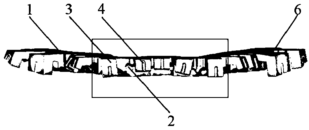
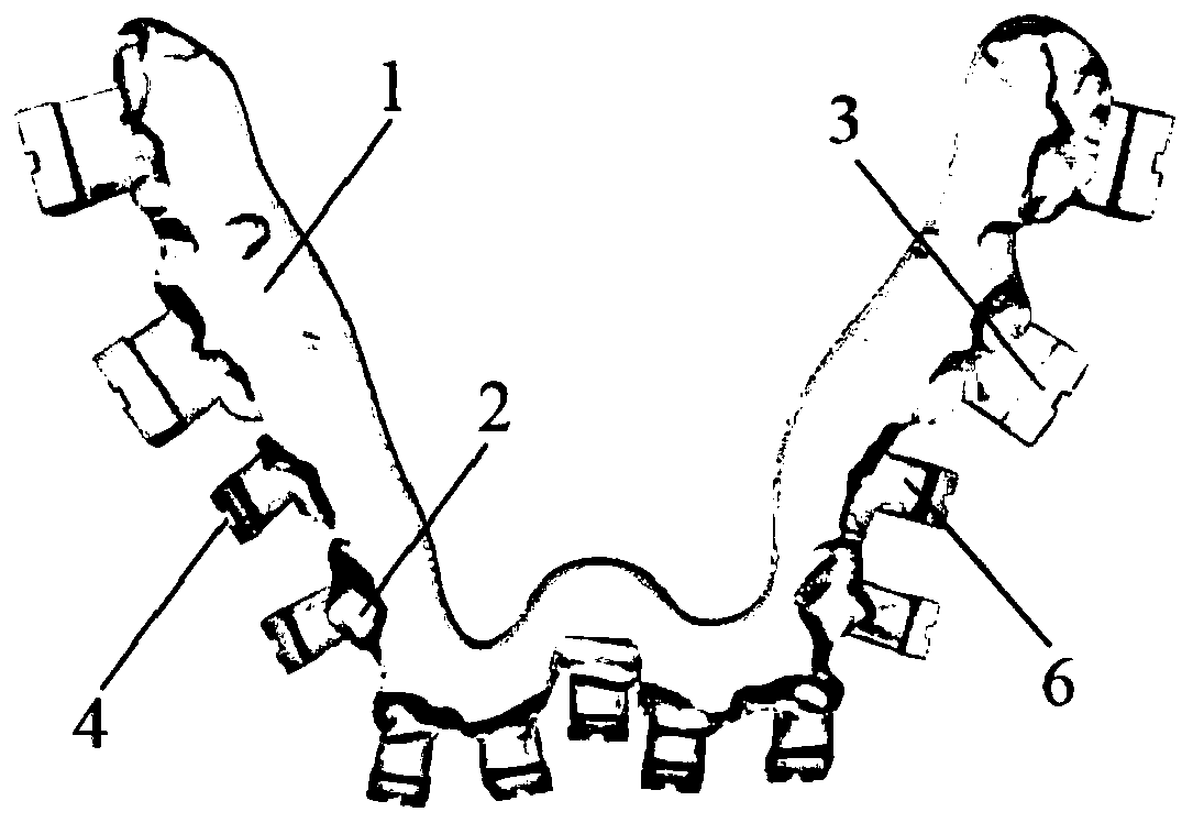
[0065] What this embodiment provides is the positioning device for guiding the bonding of the labial brackets of the mandibular 37-32, 41-47 tooth segments (31 missing teeth), its structure is as follows Figure 2-6 As shown, it is specifically composed of a plywood 1, a marking block 3 and a connecting block 6 that are fixedly connected as one.

[0066] The splint 1 of this embodiment is horseshoe-shaped, matches the shape of the orthodontic patient's gums, and has a thickness of 4 mm. There are occlusal teeth marks 2 matching the teeth of the patient's lower jaw 37-32, 41-47 on the functional surface covering the dentition. The depth is 3mm at the cusp of the 33rd tooth, 2mm at the distal buccal cusp of the 37th tooth, and 2-3mm at the anatomical parts of the rest of the teeth. The non-functional surface is a horizontal smooth surface whose outer edges on both sides match the labio-buccal surfaces of the mandibular teeth and whose inner edges match the palatolingual surfaces...

Embodiment 2

[0071] This example presents a positioning device for guiding the bonding of a single labial bracket of 12 maxillary teeth. Its structure is as follows: Figure 7-9 As shown, it is specifically composed of a plywood 1, a marking block 3 and a connecting block 6 that are fixedly connected as one.

[0072] The difference from Example 1 is: 1) The plywood 1 is oval in shape, with a thickness of 1.5mm, and the depth of the bite marks 2 is 0.5mm. The outer edges on either side of the non-functional surface match the labial and buccal surfaces of the maxillary teeth, and the inner edges match the palatoglossal surfaces of the corresponding maxillary teeth. The splint covers the incisal margin of the 12 maxillary teeth and part of the palatolingual side. 2) There is one marking block 3, which is an inverted trapezoid turned 90°, with a thickness of 1 mm, a length of 2.5 mm, and a width of 2 mm; in this embodiment, there is a guide concave in the middle of the lip and buccal side of ...

Embodiment 3

[0075] This embodiment provides a positioning device for guiding the bonding of the labial brackets of the 16-26 tooth segments of the upper jaw, and its structure is as follows Figure 10-11 As shown, it is specifically composed of a plywood 1, a marking block 3 and a connecting block 6 that are fixedly connected as one.

[0076] The difference from Example 1 is: 1) The functional surface of the splint 1 covering the dentition has an occlusal tooth mark 2 matching the patient's maxillary 16-26 teeth, see Figure 11 , the thickness of the splint 1 is 4mm, the depth of the occlusal tooth impression 2 is 0.8mm at the palatal tip of the 24th tooth, 2.5mm at the incisal edge of the 22nd tooth, and 0.8-2.5mm at the rest of the teeth. The outer edges on either side of the non-functional surface match the labial and buccal surfaces of the maxillary teeth, and the inner edges match the palatoglossal surfaces of the corresponding maxillary teeth. The splint covers the incisal edge of ...


PUM

PropertyMeasurementUnit
Thicknessaaaaaaaaaa
Depthaaaaaaaaaa
Lengthaaaaaaaaaa

Abstract

The present invention discloses a positioning device for guiding bonding of labial brackets and a manufacturing method of the positioning device. The positioning device manufactured by the method consists of a splint (1), marking blocks (3) and connecting blocks (6) which are fixedly connected into a whole, a functional surface of the splint is provided with occlusion teeth marks (2), and a non-functional surface of the splint is a horizontal smooth surface; the number of the connecting blocks (6) is the same as that of the marking blocks (3), and the connecting blocks are connected with palatoglossal side surfaces of the marking blocks (3) to form a structure with a longitudinal cross-sectional shape of a reversed L-shape or an L-shape; and a gingival end face of each marking block (3) for positioning is matched with an adjacent binding face of a bracket (7). The manufacturing method is simple and mature, and easy to popularize, the obtained positioning device is simple in structure and convenient to operate, accuracy of bracket bonding positions can be ensured from multiple angles, efficiency of clinical operation is improved, besides, the positioning device is firmer, and the positioning device is not liable to deform and damage in actual manufacturing, packaging and transportation processes.

Description

technical field [0001] The invention belongs to the technical field of orthodontic devices and their preparation, and in particular relates to a positioning device and a manufacturing method for guiding labial bracket bonding. Background technique [0002] Bracket bonding is a critical step in orthodontic treatment. Accurate and firm bonding of the brackets is conducive to the smooth development of subsequent orthodontic treatment. At present, the methods of bracket bonding are mainly divided into two categories: direct bonding and indirect bonding. Direct bonding refers to the process in which the doctor directly picks up the bracket with tweezers, and presses and bonds the bracket to a specific position on the tooth surface. Indirect bonding refers to the process in which the doctor presses the transfer device with the bracket placed in advance and sticks it in place on the tooth surface. This process uses the transfer device to assist in positioning the bracket, such as...

Claims


Application Information

Patent Timeline
IPC IPC(8): A61C7/16
CPCA61C7/002A61C7/16
Inventor 薛超然李琬延白丁韩向龙徐晖郭永文舒睿田野
Owner SICHUAN UNIV
Why Eureka
Try Eureka