Feeding and discharging device for digital controlled lathe

A CNC lathe and swing mechanism technology, applied in the field of loading and unloading, can solve the problems of unsafe manual loading and unloading, troublesome workpiece loading and unloading, and increased control process, so as to reduce the difficulty of cable laying, facilitate loading and unloading operations, and improve processing efficiency Effect

Active Publication Date: 2020-07-24
HUAINAN UNITED UNIVERSITY
View PDF5 Cites 2 Cited by
  • Summary
  • Abstract
  • Description
  • Claims
  • Application Information

AI Technical Summary

Problems solved by technology

[0004] CNC lathes generally process cylindrical workpieces. When processing workpieces, it is troublesome to load and unload workpieces. Manual loading and unloading is unsafe and inefficient. When mechanical loading and unloading is used to clamp the workpiece, multiple sets of driving mechanisms need to be used to drive the clamping parts. In order to complete the clamping and opening of the workpiece, this will increase the number of driving equipment, cables, and control processes. For this reason, a loading and unloading device for CNC lathes is required

Method used


Image

  • Feeding and discharging device for digital controlled lathe
  • Feeding and discharging device for digital controlled lathe
  • Feeding and discharging device for digital controlled lathe

Examples


Embodiment 1

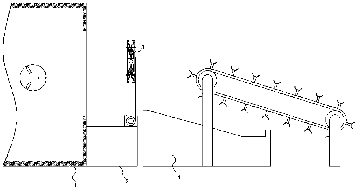
[0034] The swing mechanism 2 comprises a base arranged below the opening of the CNC lathe 1, the top of the base is provided with a rotating rod arranged along the length direction of the CNC lathe 1 through a bearing seat, and one end of the rotating rod is equipped with a first motor affixed to the top of the base, The outer ring of the rotating rod is fixedly sleeved with a swing plate, and the end of the swing plate away from the rotating rod is provided with an inner groove arranged along its length direction, and the opening of the inner groove is movably socketed with a rotating shaft fixedly socketed with the base plate 5, A second motor is installed at one end of the rotating shaft protruding from the swing plate.

Embodiment 2

[0036] The conveying mechanism 4 includes a support frame arranged on the side of the swing mechanism 2 away from the CNC lathe 1. Two groups of side baffles arranged in parallel are installed on the top of the support frame, and the side baffles are arranged obliquely. It is connected to the roller equidistantly arranged along its length direction. The outer ring of the roller is fixedly sleeved with a sprocket arranged along its length direction. The sprocket is connected with a ring-shaped chain. At least three sets of parallel For the provided chain, the outer ring of the chain is fixedly connected with a supporting plate of Y-shaped structure equidistantly arranged along its length direction, and a third motor is installed at one end where the roller protrudes from the side baffle.

Embodiment 3

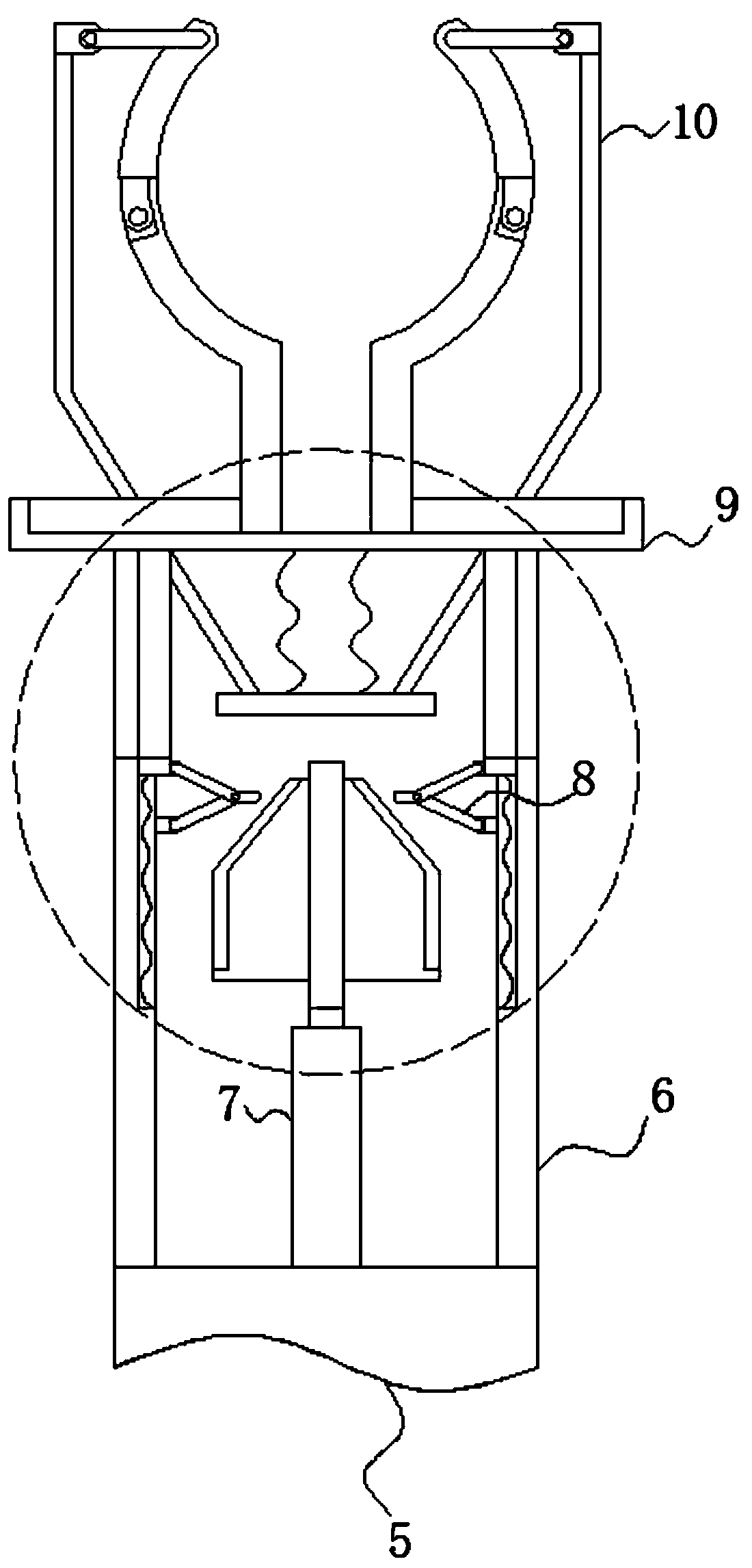
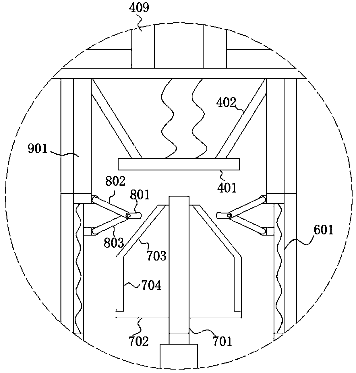
[0038] The pull rod 402 includes a sleeve fixedly connected to the bottom of the cross bar 403. One end of the sleeve away from the cross bar 403 is movably sleeved with a telescopic rod affixed to the top of the push plate 401, and the outer ring of the end close to the telescopic rod is movably socketed with a A second spring fixed to the bottom of the cover plate 9 is installed on the top of the push plate 401 as the rotating collar threadedly connected with the outer ring of the telescopic rod.


PUM


Abstract

The invention belongs to the technical field of feeding and discharging and particularly relates to a feeding and discharging device for a digital controlled lathe. The following scheme is proposed. The feeding and discharging device comprises the digital controlled lathe and a swing mechanism arranged at an opening of the digital controlled lathe. The swing mechanism is provided with a clamping assembly for clamping a workpiece, the side, away from the digital controlled lathe, of the swing mechanism is provided with a conveying mechanism, and the clamping assembly comprises a baseplate connected with an output end of the swing mechanism. The two ends of the baseplate are provided with a housing symmetrically arranged along the baseplate, a pushing mechanism fixedly connected with the baseplate is installed in the middle in the housing, the two sides of the end, away from the baseplate, of the pushing mechanism are provided with abutting mechanisms, the opening of the housing is provided with a cover plate, and a clamping mechanism is arranged on the end, away from the housing, of the cover plate. According to the feeding and discharging device, mutual interference and collision of a clamping part and a workpiece are avoided, the safety of the equipment and the workpiece is guaranteed, the difficulty of controlling the equipment is lowered, the difficulty of laying a cable islowered, the workpiece is conveniently fed and discharged, the efficiency of machining the digital controlled lathe is improved, and the labor intensity of operators is lowered.

Description

technical field [0001] The invention relates to the technical field of loading and unloading, in particular to a loading and unloading device for a numerically controlled lathe. Background technique [0002] CNC lathe is one of the most widely used CNC machine tools at present. It is mainly used for cutting the inner and outer cylindrical surfaces of shaft parts or disk parts, the inner and outer conical surfaces of arbitrary cone angles, the complex rotary inner and outer curved surfaces, cylinders, and conical threads, etc., and can perform grooving, drilling, reaming, and reaming. Holes and borings etc. [0003] The CNC machine tool automatically processes the processed parts according to the pre-programmed processing program. We write the processing route, process parameters, tool trajectory, displacement, cutting parameters and auxiliary functions of the parts into a processing program sheet according to the instruction code and program format specified by the CNC mac...

Claims


Application Information

Patent Timeline
Patent Type & Authority Applications(China)
IPC IPC(8): B23B15/00
CPCB23Q7/00B23Q7/04B23Q7/043B23Q7/048
Inventor 李晟锴孙晓东李娟
Owner HUAINAN UNITED UNIVERSITY
Why Eureka
Try Eureka